
In brief
Air traffic is about the safety of flight operations: pilots on approach, at touchdown and while taxiing, as well as control tower staff, should not be dazzled. Criteria are given by the EASA aerodrome design specifications (permissible luminance 20,000 cd/m²) and the policy of the US Federal Aviation Administration FAA (no glare in the control tower cab). In the app, the approach is entered as a "Flight Route" with a tilted field of view; section VI.4.6 leads step by step from the values of the approach chart to the result. We welcome references to further guidelines at info@pv-glarecheck.com.
VI.4.1 Protected interest and typical glare situations
Observers are pilots in the air and on the ground and the personnel in the control tower. EASA names as critical (CS-ADR-DSN, GM1 ADR-DSN.M.615 (i)–(j)):
- the approach, especially after passing the decision height: the pilot should not lose visual reference,
- touchdown: the pilot should not be surprised by a flash of light,
- taxiing after landing and before take-off: the pilot should perceive the surroundings and recognize deviations from the center line,
- the control tower: glare should not reduce the perception of flight operations on and near the runway.
Situations in which disturbing glare can occur: PV systems on or next to the aerodrome (between runways, on hangar roofs, along fences), below or beside the extended runway center line on final approach, in the area of traffic circuits of small aerodromes, and within sight of the control tower.
VI.4.2 Guidelines at a glance
| EASA CS-ADR-DSN (EU) | FAA Policy 2021 (USA) | FAA Interim Policy 2013 (USA, superseded) | |
|---|---|---|---|
| Edition, status | Issue 7 (ED Decision 2025/004/R), applicable since 24.05.2025; same wording in Issue 4 and 6; guidance material (GM) | in force since 11.05.2021; supersedes the Interim Policy; by its own statement without force of law | 23.10.2013; still used in reports and software |
| Scope | aerodromes within the scope of the EASA rules | federally-obligated airports with a control tower, systems on airport property | as 2021, plus final approach |
| Observers | pilots on approach, at touchdown and while taxiing; air traffic controllers | control tower cab | control tower cab and final approach |
| Criterion | luminance at most 20,000 cd/m² | no glare in the cab | tower: no glare; final approach: at most low potential for after-image |
| Field of view | regions up to 90°, 60° and 30° around the viewing direction, task field 1° to 2° | not specified | not specified |
| Approach geometry | exact adherence to the flight path assumed; no dimensions | none (approach not covered) | 2 miles from 50 ft above the threshold, 3° glide path |
| Duration, time resolution | not specified | not specified | whole year, 1-minute steps, sunrise to sunset |
| Tool | no requirement | no requirement; analysis recommended, submission not required | SGHAT (withdrawn) |
References are given in sections VI.4.3 and VI.4.4. Austria (OVE R 11-3), Switzerland (notes of the FOCA) and Italy (ENAC) are summarized in VI.4.5. For Germany, the sources evaluated contain no quantitative criterion of their own; reports often rely on CS-ADR-DSN, and the requirements follow case by case from the procedure with the competent aviation authority.
Not regulated in any source: eye heights, a vertical field of view for assessing PV reflections, overlap with the sun, helicopters, visual flight away from published procedures, night operations and weather. In addition, EASA gives no duration and no approach dimensions, and FAA 2021 gives no criteria for pilots, no measured quantity and no tower geometry.
VI.4.3 EASA CS-ADR-DSN (EU)
The notes are in the guidance material on aerodrome lighting, GM1 ADR-DSN.M.615 "General", letters (h) to (l) (Issue 7, pp. 159–160; Issue 6, pp. 161–162):
- Field of view (h)(3): field of perception up to about 90° to each side of the viewing direction, field of visibility up to 60°, field of conspicuity up to 30° (recognition) and task field close around the viewing direction at 1° to 2° (identification). For 60° and 30°, the text does not state explicitly whether the angle applies to each side.
- Hazard situations (i): glare from veiling luminance should not occur on approach (shortly before the decision height) or while taxiing; at touchdown there should be no surprise effect.
- Air traffic controllers (j): veiling glare should not reduce the perception of flight operations on and near the runway.
- Solar panels (k): the considerations can be applied to solar panels. The permissible maximum luminance is set at 20,000 cd/m²; areas from 100 m² up to several hectares were considered.
- Flight path (l): the aircraft is assumed to follow its flight path exactly; in reality the approach runs within a cone-shaped region around the nominal path.
VI.4.4 FAA (USA)
VI.4.4.1 Policy 2021
Scope (86 FR 25802–25803): proposed solar systems on the property of airports that have received federal funding (federally-obligated) and have a control tower. Not covered are airports without a control tower, airports without this obligation, and systems outside airport property; their sponsors are encouraged to consider the glare impact on nearby control towers and to coordinate with the airport operator.
Requirement (p. 25803): in Form 7460-1 (Notice of Proposed Construction or Alteration), the airport operator declares that the system causes no glare (glint or glare) in the control tower cab. A glare analysis before submission is recommended; its results need not be submitted. No specific tool is prescribed; the previously required Solar Glare Hazard Analysis Tool (SGHAT) has been withdrawn. If the system is not visible from the tower, for example because a building blocks it, no tool is needed. If impacts on the tower are found after construction, the operator must remove them at its own expense.
Approach (p. 25802): the FAA concludes that glare from solar systems for pilots on final approach is in most cases similar to glare from water surfaces, glass façades or parking lots. Final approach is therefore no longer covered by the policy.
Technical guidance. The FAA Technical Guidance for Evaluating Selected Solar Technologies on Airports (April 2018 version) states that there are no specific standards for solar systems and glare, and names three levels of assessment: qualitative assessment with tower, pilots and airport; field test with panels at the planned site; geometric analysis of the days and times of possible glare (section 3.1.2, pp. 38–40).
VI.4.4.2 Interim Policy 2013 (superseded)
The 2013 criteria are still in use and are therefore listed for context (78 FR 63277):
- no glare in the existing or planned control tower cab,
- along the final approach no glare, or only glare with "low potential for after-image" (green zone of the assessment chart),
- final approach defined as 2 miles from 50 ft above the landing threshold on a 3° glide path,
- analysis over the whole calendar year in 1-min steps from sunrise to sunset.
For this, the SGHAT evaluated the retinal irradiance and the subtended angle of the glare source and assigned the results to hazard levels from temporary after-image to retinal burn (78 FR 63277–63278).
VI.4.5 Further guidelines and literature
Austria. OVE R 11-3 (edition 01.11.2016, withdrawn as of 01.12.2024, unofficially often still applied for orientation) requires that glare during approach, departure and taxiing, confusion with aerodrome lighting, and impairment of air navigation services and airspace surveillance be prevented; the legal basis is § 94 of the Austrian Aviation Act, with the aviation authorities and Austro Control involved (section 6.2.3, pp. 12–13). The guideline gives no numerical values.
Switzerland. According to the EnergieSchweiz report 2024, systems are considered uncritical under notes of the FOCA (BAZL) if their area in square meters is smaller than the distance in meters to the nearest immission point; landing aircraft must not be dazzled head-on; the critical areas are published on map.geo.admin.ch (state of the art for low-glare surfaces of PV modules, p. 30). The 2023 guide on the notification and permit procedure contains no rules for air traffic.
Italy. The ENAC guideline LG–2022/002-APT (edition 1 of 26.04.2022, not binding) allows a qualitative or a quantitative assessment. Acceptance criteria include no glare with after-image potential on any flight path from the runway threshold up to 3 km distance, and no glare at the height of the control tower cab (section 5.6, pp. 37–38).
Literature. In an FAA simulator study with general aviation pilots, glare on final approach was presented at 0°, 25°, 50° and 90° from the straight-ahead viewing direction. The closer the glare was to the viewing direction, the more severe the impairment was rated; the authors recommend placing glare sources so that they do not dazzle on approach from angles below 50° to the straight-ahead viewing direction (Rogers et al. 2015, DOT/FAA/AM-15/12, discussion, p. 9). The study is not a guideline.
VI.4.6 Procedure in PV-GlareCheck
Note on application. The following settings are conceivable interpretations and examples of application of the guidelines, not a binding implementation. Which guideline applies and how it is correctly interpreted and applied in the individual case must be verified independently by the user.
The sections follow the order of the work: check documents and reflection directions (VI.4.6.1), define the observers (VI.4.6.2), draw the approach (VI.4.6.3), add further flight paths and the control tower (VI.4.6.4), choose module type and occlusion (VI.4.6.5), calculate (VI.4.6.6), filter (VI.4.6.7) and read the result (VI.4.6.8). VI.4.6.9 shows a calculated example.
VI.4.6.1 Preparation
- Aerodrome documents. For each runway, the position and elevation of the landing threshold, the landing direction and the glide angle are needed; for the control tower, its position and the controllers' eye height above ground. They are given in the approach charts and aerodrome documents.
- Check reflection directions. In the pre-analysis (Ch. 11), "Max" of the "Angle Filter (Reflection Direction)" is raised to 30° to 45°, because reflections towards aircraft go upwards. The cones then show which approach and departure paths lie in a reflection direction at all. Paths that no cone reaches need no points.
VI.4.6.2 Observers and groups
Each observer is entered as a separate group of observation points (Ch. 9): one group per runway and approach direction, likewise per departure, traffic circuit, taxiway and for the control tower. Each group is filtered and evaluated separately in the report.
| Observer | Entry method | Length and position | Height | Field of view |
|---|---|---|---|---|
| Approach | "Flight Route" (Pro) | from the threshold against the landing direction, about 2 to 4 nautical miles (see below) | linear from 15.2 m above the threshold to the height at the far end (VI.4.7.1) | in flight direction, "Tilt" = glide angle, "H±" 50° |
| Departure | "Flight Route" (Pro) | from the runway end in the departure direction; no source gives a length | rising according to the departure procedure | in flight direction |
| Traffic circuit | "Flight Route" (Pro) | along the published traffic circuit, one group per flight direction | according to the chart | in flight direction |
| Taxiing | "Points along a line" | runway center line or taxiway | cockpit eye height above ground | in taxiing direction |
| Control tower | "Place single points" | at the cab | controllers' eye height above ground | none (FAA) or towards the runway (EASA) |
Length of the approach. EASA gives no length. According to EASA, the critical phase is the approach shortly before reaching the decision height until touchdown, and it assumes an exactly maintained flight path (VI.4.3). This leaves room for interpretation. At large airports the decision height lies about 0.5 to 1 nautical mile before the landing threshold; a consideration of 2 to 4 nautical miles (3.7 to 7.4 km) up to the threshold includes this section. The FAA Interim Policy 2013 considered 2 miles (3.2 km), the ENAC guideline 3 km from the threshold (VI.4.4, VI.4.5).
For departure, traffic circuit and taxiing, the sources give neither geometry nor eye heights.
VI.4.6.3 Drawing the approach
EASA assumes an idealised final approach: straight, in line with the extended runway center line, on a uniform glide path. If the approach chart shows such a straight final approach for the distance considered, it can be modelled with a single "Flight Route". The following example assumes a runway with landing direction 256°, threshold elevation 120 m above sea level, glide angle 3° and a length of 3 nautical miles.
1. Values from the approach chart.
| Value | Designation on the chart | Example |
|---|---|---|
| Position of the landing threshold | threshold (THR), coordinates | from chart or aerial image |
| Landing direction | runway direction (QFU) | 256° |
| Threshold elevation | THR ELEV | 120 m |
| Glide angle | glide path (GP) | 3° |
| Threshold crossing height | TCH or RDH | 50 ft = 15.2 m |
2. Calculate heights. The height above the threshold increases with the distance d: h = 15.2 m + d · tan 3°. At 3 nautical miles (5,556 m) this is 15.2 m + 291 m = 306 m. Further values are given in VI.4.7.1.
3. Create a group. In the "Observation Points" menu, create a group with "New group" and name it, for example "Approach runway 26".
4. Fill in the "Flight Route" dialog. In the group, choose "Flight Route" and enter:
- "Distance between points": about 200 m;
- "Height reference": "Above Mean Sea Level (AMSL)", so that the glide path stays straight even over uneven terrain;
- "Flight altitude start": 135 m (threshold elevation 120 m + 15.2 m), "Flight altitude end": 426 m (120 m + 306 m);
- leave "Always end line with a point" switched on, so that there is also a point at the far end;
- switch on "Enable and align fields of view along the line" and choose "Against drawing direction", because the route is drawn from the threshold while the pilot looks towards the threshold.
In flat terrain, "Above Ground Level (AGL)" with 15 m and 306 m can be chosen instead.
5. Draw the route. The first click places the start point on the landing threshold. Then move the mouse pointer along the extended runway center line away from the aerodrome. The display above the map shows "Total" (length of the route) and "Azimuth" (direction of the segment). The direction away from the aerodrome is the reverse of the landing direction, here 76°. At "Total" 5.56 km, finish with a double-click. The app distributes the points at the chosen distance and interpolates the height linearly between start and end point.
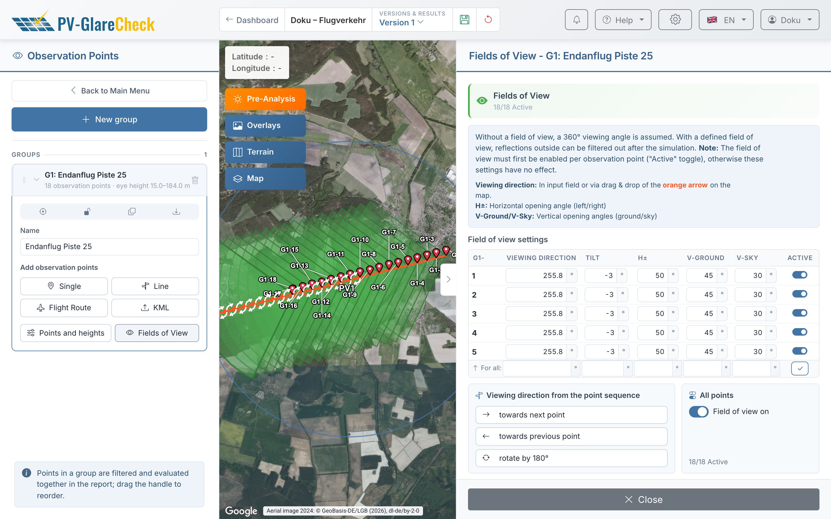
6. Adjust the field of view. In the group's "Fields of View" panel, use "For all:" to set "Tilt" to −3° (looking down along the glide path) and "H±" to 50°. When switching on, the app had set "Tilt" to 0° and "H±", "V-Sky" and "V-Ground" to 30° each. "V-Sky" and "V-Ground" depend on the view from the cockpit and are entered explicitly.
7. Check. "Points and heights" shows the height above ground level for each point; with "Above Mean Sea Level (AMSL)" the app has subtracted the ground level. If a point lies below ground level, a warning appears. The point at the threshold carries about 15 m, the far point about 306 m, both calculated above the threshold elevation.
If, according to the chart, the final approach deviates from the runway center line or has a bend, it is composed of several routes, one per straight section.
Point spacing. No source gives a spacing. 200 m gives 18 points over 2 miles, 100 m gives 34 (including the end point). Where the route passes the installation, a second, denser route can be added. The limit is 100 points per simulation in the Pro plan.
Field-of-view values. "H±" 50° corresponds to the recommendation of Rogers et al. (2015) not to place glare sources below 50° from the straight-ahead viewing direction, and lies between the conspicuity field (30°) and the visibility field (60°) of EASA; the value is an assumption, not a requirement. The "Tilt" shifts the vertical viewing window and is the reference axis for the distance to the gaze axis in the report.
VI.4.6.4 Departure, traffic circuit, taxiing and control tower
- Departure: like the approach, with rising height from the runway end in the departure direction; one group per departure direction.
- Traffic circuit: "Flight Route" along the published traffic circuit, with "Above Mean Sea Level (AMSL)" if the chart gives heights above sea level. A route interpolates the height only linearly; turns and changes of height are composed of several routes.
- Taxiing: "Points along a line" along the runway center line or the taxiways, the cockpit eye height as "Height a. GL", field of view in taxiing direction.
- Control tower: one or more points with "Place single points" at the cab, with the controllers' eye height above ground. For the FAA question of whether glare occurs in the cab at all, the field of view stays off; the app then evaluates all directions. For the EASA question of the perception of operations on and near the runway, a field of view towards the runway can be set.
VI.4.6.5 Module type and occlusion
- Module type (Ch. 8): For the EASA luminance criterion (20,000 cd/m²), a real module type with a measured module profile is needed; with "Perfect mirror" every reflection has the luminance of the sun. Also for the question of whether glare occurs at all (FAA, control tower), "Perfect mirror" is not the least favourable assumption: a real module type with beam spread reflects more widely and reaches more points and time steps.
- Occlusion: Buildings, hangars, embankments and vegetation between the installation and the flight path, taxiway or tower are entered as obstacles (Ch. 10.1), terrain via terrain occlusion (Ch. 6). If the installation is completely hidden from the tower, according to the FAA this is a reason not to use a tool; the simulation can document the occlusion.
VI.4.6.6 Simulation
The simulation always calculates a whole year in time steps of 1 min with a cloudless sky (Ch. 12, Ch. V.1). This corresponds to the period and time resolution of the Interim Policy 2013; a shorter period cannot be set and is not needed, because the report shows the days and times with glare. PV areas must lie within 3 km of the centre of the project area (Ch. 5); observation points may lie outside, so a long approach does not have to fit into the project area.
VI.4.6.7 Possible filter combinations
The table shows one possible filter combination per guideline. It lists the filters that can be derived from the guideline, and filters that are switched on in a new report and are switched off for it. Further filters (Ch. V.8) can be added at the user's discretion where they are professionally justified. The filters are set per group in the report under "Evaluation method" with "Edit filters" (Ch. 14).
| Filter ("Evaluation method") | FAA 2021, control tower | EASA, approach and taxiing | EASA, control tower |
|---|---|---|---|
| "PV area shaded" | on | on | on |
| "Reflection blocked by obstacle" | on | on | on |
| "Outside field of view" | no effect (no field of view) | on (pilot's field of view) | on (field of view towards the runway) |
| "Luminance" ≥ | off | 20,000 cd/m² | 20,000 cd/m² |
The "Luminance" filter is switched on at 30,000 cd/m² in a new report. In the FAA 2021 column it is off, because every glare counts there; in the EASA columns it is set to 20,000 cd/m².
VI.4.6.8 Reading the result
| Quantity in the report | Reference |
|---|---|
| "—" or "0" in the group table, "Total glare duration per year" | Does glare occur at the tower or along the flight path at all (FAA 2021, ENAC)? "—": no reflection; "0": reflections, but all removed by the filters |
| "Peak luminance" | comparison with 20,000 cd/m² (EASA) |
| "Min. gaze axis distance" with the values H and V | position relative to the tilted gaze axis; comparison with 30° (EASA) or 50° (Rogers et al. 2015) |
| "Peak illuminance" | amount of light at the eye |
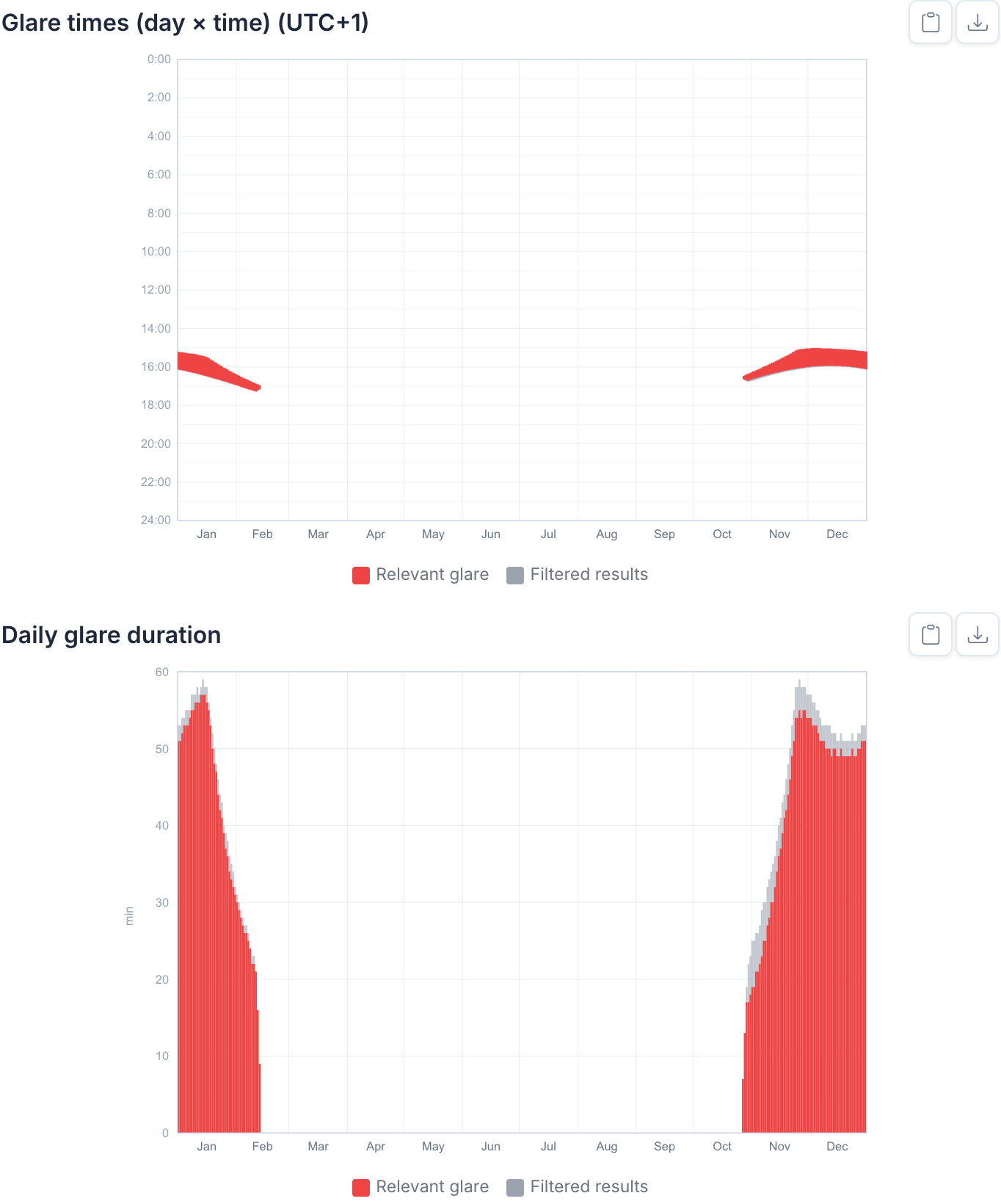
| "Glare times (day × time)", "Daily glare duration" | days and times of possible glare (geometric analysis according to FAA 2018) |
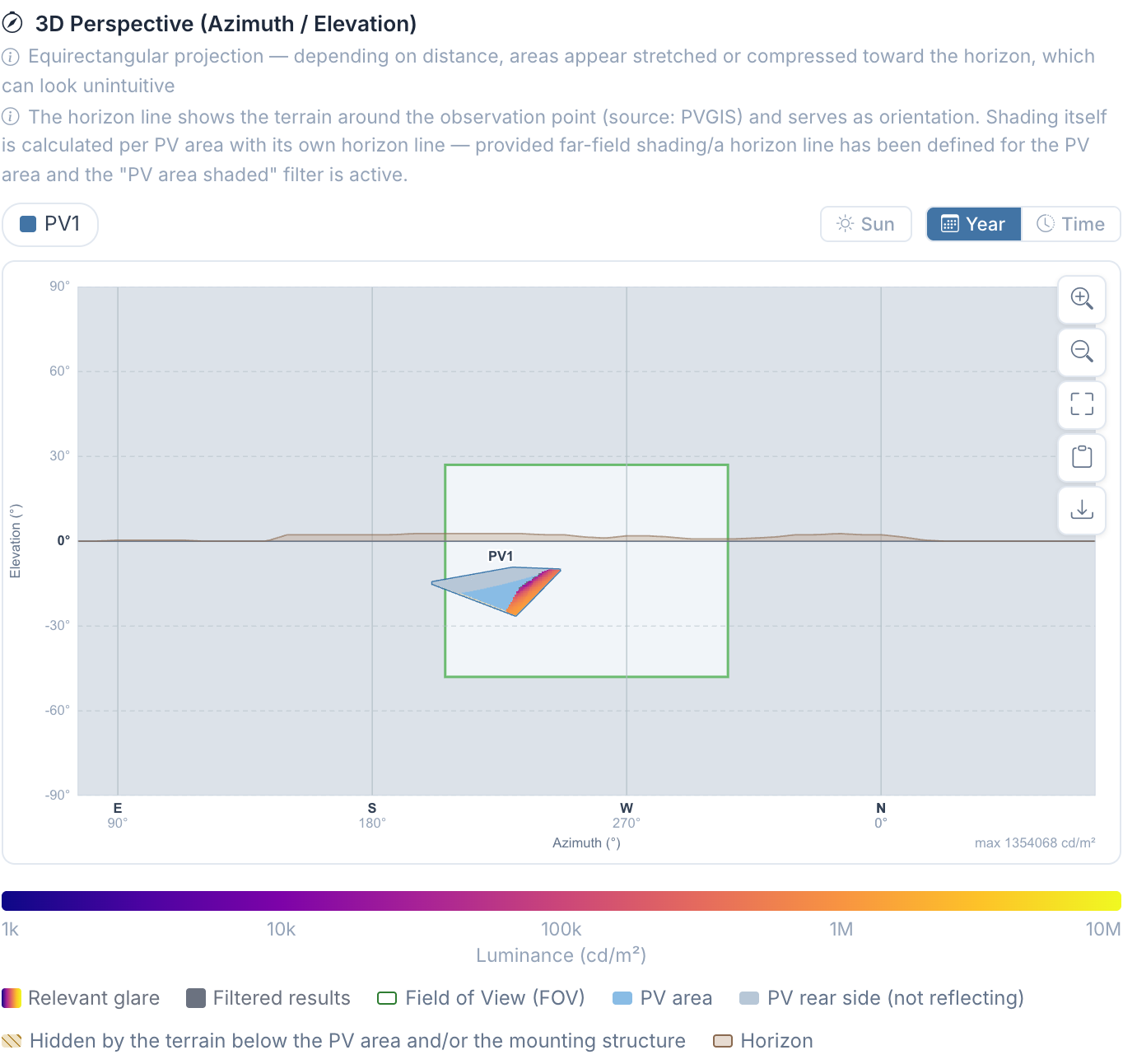
| "3D perspective (azimuth / elevation)" | position of the glare source in the field of view |
Each point of the route is stationary. The duration at a point is the time during which a reflection would be visible at this position on the path, not the time a pilot sees a reflection while flying past.
VI.4.6.9 Example
Ground-mounted system with azimuth 180° and tilt 20°, module type "Standard Module", 0.95 to 1.25 km before a runway threshold and 80 to 230 m to the side of the extended runway center line. Final approach as a "Flight Route" over 2 miles (3.2 km) on the 3° glide path, in flat terrain with "Above Ground Level (AGL)" from 184 m to 15 m, points every 200 m; field of view in flight direction with "Tilt" −3°, "H±" 50°, "V-Ground" 45°, "V-Sky" 30°. Filters according to EASA as above. Calculated as an example project with a fictitious system.
- Before the system (points G1-7 to G1-11, 2.0 to 1.2 km before the threshold, about 120 to 80 m above ground), reflections lie in the field of view, the closest 7.3° from the gaze axis. Most affected is G1-10, 1.4 km before the threshold: from late October to early February in the afternoon, up to 57 min per day. The luminance reaches up to 1.35 million cd/m² and thus exceeds the 20,000 cd/m² of CS-ADR-DSN.
- Above and behind the system (G1-12 to G1-18), reflections come only from behind (110° to 166° from the gaze axis); after the "Outside field of view" filter, 0 min remains.
- Further away (G1-1 to G1-6), no reflection occurs ("—").
VI.4.7 Notes
VI.4.7.1 Heights of the glide path
The height above the threshold is h = 15.2 m + d · tan γ, with 15.2 m (50 ft) threshold crossing height, d as the distance to the threshold and γ as the glide angle. For 3° this gives:
| Distance to the threshold | Height above the threshold |
|---|---|
| 0.5 nautical miles (926 m) | 64 m |
| 1 nautical mile (1,852 m) | 112 m |
| 2 miles (3,219 m) | 184 m |
| 2 nautical miles (3,704 m) | 209 m |
| 3 nautical miles (5,556 m) | 306 m |
| 4 nautical miles (7,408 m) | 403 m |
- "Above Ground Level (AGL)": The heights apply above ground level at each point. In flat terrain, the values of the table are entered; over uneven terrain the path follows the terrain.
- "Above Mean Sea Level (AMSL)": The heights are absolute; threshold elevation plus 15.2 m is entered at the threshold and threshold elevation plus the table value at the far end. The app subtracts the ground level at each point; the glide path stays straight.
Other glide angles and threshold crossing heights follow from the aerodrome's procedures; the formula then applies with these values.
VI.4.7.2 Limits of the modelling
- After-image potential: the app calculates no retinal irradiance and no classification by after-image potential. The criteria of the Interim Policy 2013 (green zone) and of the ENAC guideline therefore cannot be represented directly. Available are luminance, illuminance at the observation point and the apparent size of the source (Ch. V.5).
- Moving observer: Each point is stationary (VI.4.6.8). Deviations from the nominal path (EASA (l)) are only captured via additional routes.
- Linear height: the flight route interpolates the height linearly between start and end point. Curved paths, steps or turns with height changes are composed of several routes.
- Cockpit: frame, windows, instrument panel and aircraft attitude (pitch and bank) are not modelled; the field of view is a rectangle in azimuth and elevation around the tilted axis.
- Tower glazing: anti-reflective glass and glare protection in the cab are not taken into account.
VI.4.7.3 Settings in the report
The report itself documents the settings used (Ch. 14):
- the filters per group as filter cards under "Evaluation method",
- for each observation point the position, terrain height, observer height and, where applicable, the field of view in the chapter "Observation Points", including the points of a "Flight Route" and at the control tower,
- module types with their characteristic curves in the appendix,
- version and calculation state on the cover page.
The points of a "Flight Route" carry their height as "Height a. GL"; with "Above Mean Sea Level (AMSL)" this is the flight altitude minus ground level.
VI.4.8 Sources
- European Union Aviation Safety Agency: Certification Specifications and Guidance Material for Aerodromes Design (CS-ADR-DSN), Issue 7 (ED Decision 2025/004/R); previously Issue 6 (ED Decision 2022/006/R) and Issue 4 (ED Decision 2017/021/R).
- Federal Aviation Administration: Federal Aviation Administration Policy: Review of Solar Energy System Projects on Federally-Obligated Airports. Federal Register Vol. 86, No. 89, 11.05.2021, pp. 25801–25803 (FR Doc. 2021-09862).
- Federal Aviation Administration: Interim Policy, FAA Review of Solar Energy System Projects on Federally Obligated Airports. Federal Register Vol. 78, No. 205, 23.10.2013, pp. 63276–63279.
- Federal Aviation Administration: Technical Guidance for Evaluating Selected Solar Technologies on Airports, November 2010, updated April 2018.
- OVE: OVE-Richtlinie R 11-3 "Blendung durch Photovoltaikanlagen", edition 2016-11-01 (withdrawn 2024-12-01).
- ENAC: Linee Guida LG–2022/002-APT "Valutazione degli impianti fotovoltaici nei dintorni aeroportuali", edition 1, 26.04.2022.
- EnergieSchweiz: Stand der Technik zu blendarmen Oberflächen bei PV-Modulen, October 2024.
- Rogers, J. A.; Ho, C. K.; Mead, A.; Millan, A.; Beben, M.; Drechsler, G.: Evaluation of Glare as a Hazard for General Aviation Pilots on Final Approach. FAA Office of Aerospace Medicine, DOT/FAA/AM-15/12, 2015.