
In brief
An observation point is the location where glare is checked, for example a window, a traffic lane or a point on the approach path. It has a position, an eye height and optionally a viewing direction (field of view). Points belong to groups, which are evaluated together in the report.
9.1 How to
- In the "Observation Points" menu, create a group with "New group" and name it, e.g. "Residential building north, upper floor" or "B 32 southbound".
- Set points with one of the input methods (table below).
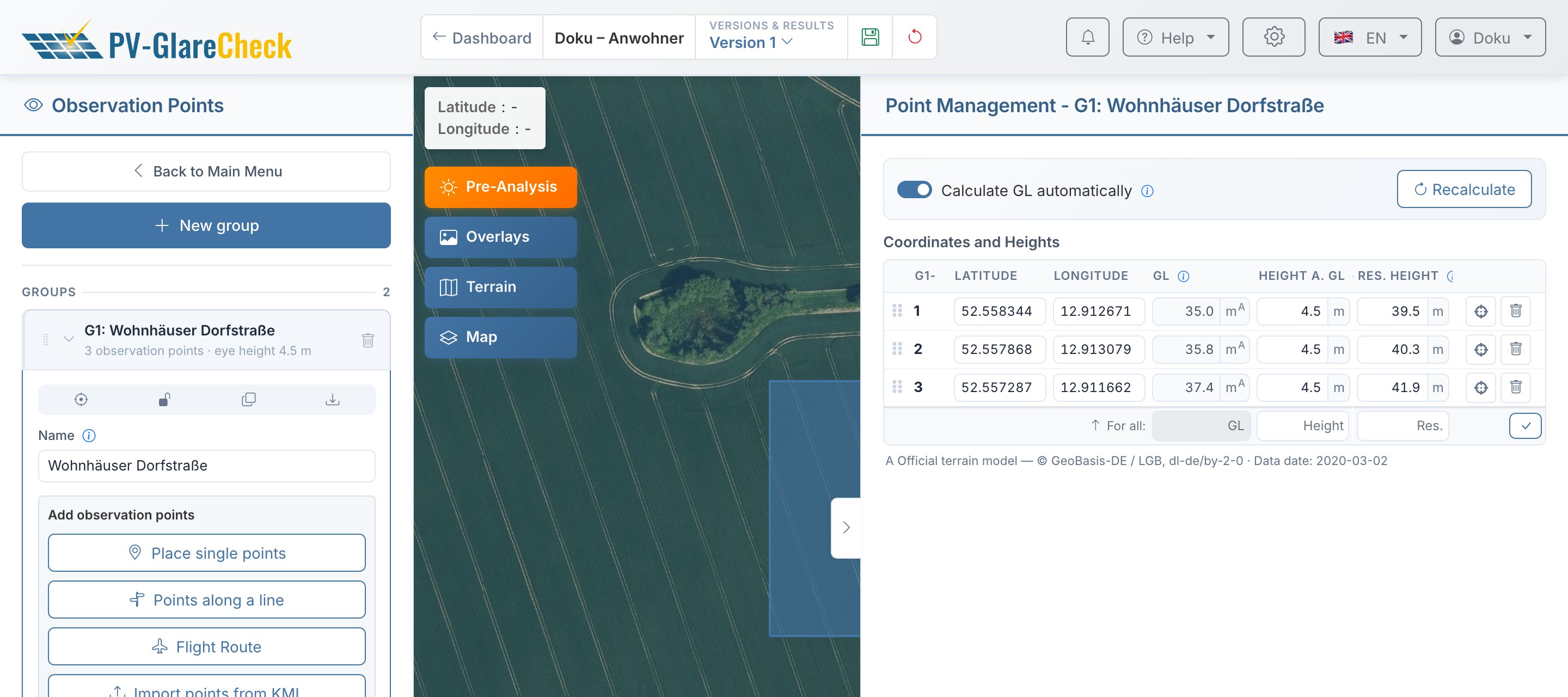
- Under "Points and heights", enter the eye height. The GL comes automatically from the elevation data; the height above GL is mandatory for every point.
- Optionally, set the viewing direction under "Fields of View" (section 9.4).
- The to-do list shows per group how many points still lack a height.
| Method | Suitable for |
|---|---|
| "Place single points" | windows, balconies, towers: each click on the map sets a point |
| "Points along a line" | roads, paths, railway lines: points at a fixed spacing along a drawn line, optionally with a field of view in the direction of travel |
| "Flight Route" (Pro) | approach and departure: like "Points along a line", additionally with a height from start point to end point |
| "Import points from KML" | points from a KML or KMZ file, e.g. from Google Earth |
9.2 Groups
The report filters and assesses per group. A group therefore combines points that are assessed in the same way: a building or floor, a road per direction of travel and vehicle type, an approach path. The group determines the ID: "G2-5" is the fifth point of the second group. It appears on the map, in the report and in the Excel export.
For variants of the same row of points, such as cars and trucks on the same road, the group is copied with the "Duplicate group" button on the group card, and only the height is changed in the copy.
9.3 Height
The simulation calculates with the resulting height: GL plus height above GL. That is where the observer's eye is.
| Field | Meaning |
|---|---|
| "GL" | terrain elevation in m a.s.l., automatically from the elevation data (Ch. 6) |
| "Height a. GL" | eye height above the terrain, for buildings including the floor; mandatory, 0 m is allowed |
| "Res. Height" | GL plus height above GL; a known absolute eye height (building plan, tower) can be entered here directly |
Eye heights given by guidelines or practice:
| Situation | Height above GL | Source |
|---|---|---|
| Car driver | 1.0 m above road surface | FBA position paper, ch. 4, p. 7 |
| Truck driver | at least 2.7 m above road surface | FBA position paper, ch. 4, p. 7 |
| Train driver | approx. 2.5 m above top of rail | rough guide value, no source (Ch. VI.3) |
| Undeveloped building plot | 2 m (LAI) or the building height permitted under building law (OVE), at the most affected edge | Ch. VI.1 |
| Window, balcony | no specification; include the floor height | Ch. VI.1 |
"For all:" below the table applies one height to all points of the group.
9.4 Field of view
A field of view describes where the observer looks. It does not restrict the calculation: the simulation captures all reflections, and the report can count only those within the field of view with the "Outside field of view" filter. Without a field of view, the point is treated as looking in all directions.
In road and rail traffic and on the approach path, the guidelines assess glare within the field of view; for residents, LAI and OVE do not provide for a field of view (Ch. VI.1 to Ch. VI.4).
| Value | Meaning |
|---|---|
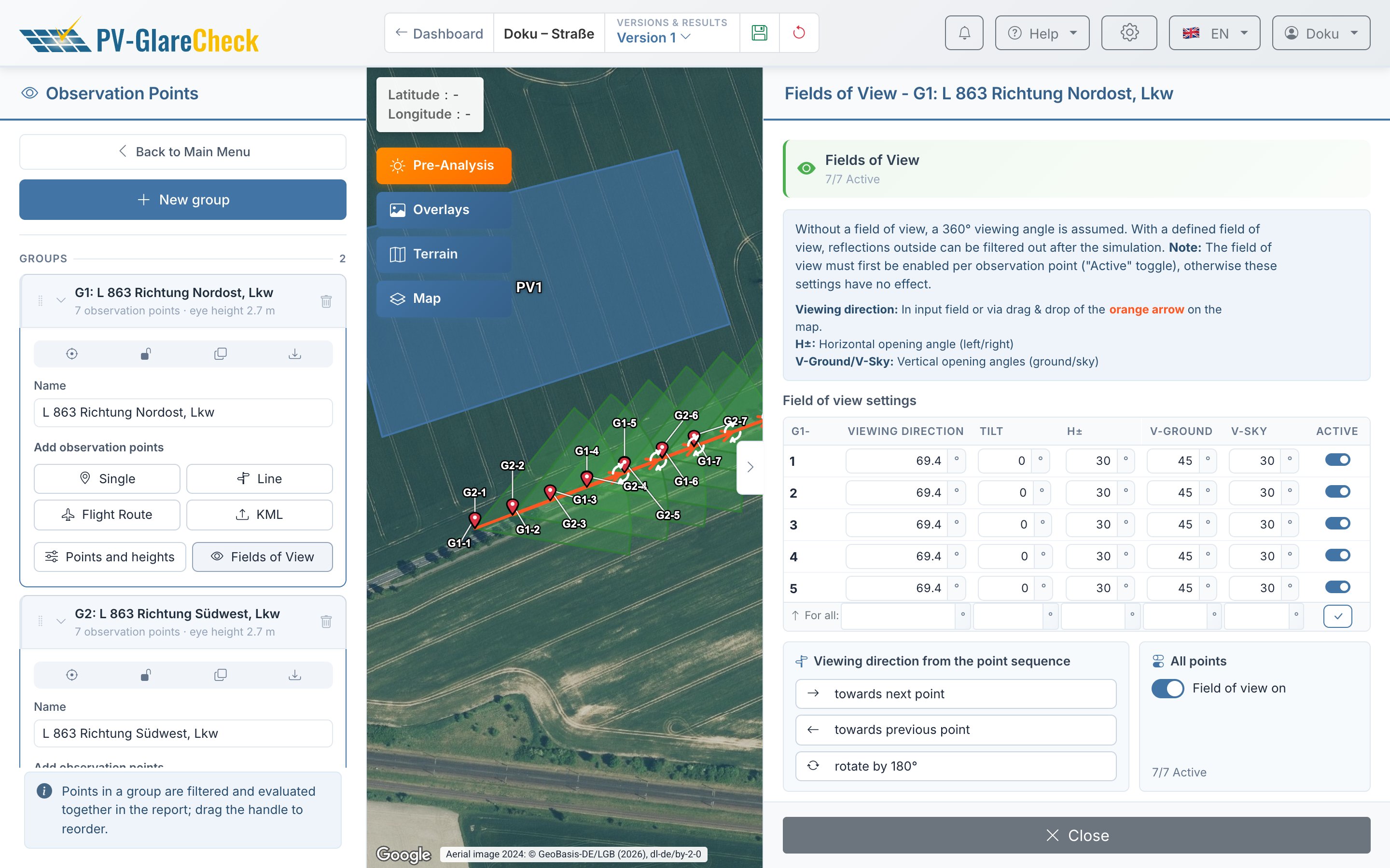
| "Viewing Direction" | viewing direction as azimuth, 0° = north, clockwise |
| "Tilt" | tilt of the gaze axis; 0° horizontal, negative downwards (approach) |
| "H±" | opening to each side, e.g. 30° according to the position paper |
| "V-Ground", "V-Sky" | opening downwards and upwards, from the gaze axis |
When switched on, "H±", "V-Sky" and "V-Ground" are 30° each and the tilt is 0°. The viewing direction has no default: if it is missing, a to-do blocks the start. Allowed are "H±" 1° to 180° (180° = all-round view), "V-Sky" and "V-Ground" 1° to 90°, the viewing direction 0° to 360° (360° = north) and the tilt −90° to 90°. An invalid value is marked red in the field and not applied; older projects with invalid values block the start as a to-do until they are corrected.
The field of view is a rectangle of azimuth and elevation range, not a cone. The tilt only shifts the elevation range, e.g. at −3°, "V-Ground" 20° and "V-Sky" 10° to −23° to +7°; the azimuth range stays the same (Ch. V.6).
Points created via "Points along a line" with a field of view get the direction of the line segment and the other values as when switching on. In the "Fields of View" panel, "towards next point" aligns each point with the following one (direction of travel, also in curves); "rotate by 180°" gives the opposite direction.
For points with a field of view, the report shows the min. gaze axis distance: the smaller it is, the more central the glare lies in the field of view.
9.5 Points to note
- Bridges, embankments, floor slabs: The GL from the elevation data is the ground below. There, switch off "Calculate GL automatically" and enter the height of the carriageway or floor by hand. Jumps in GL between neighboring points indicate this.
- KML import replaces all existing points of the group.
- Fields of view are fixed with the simulation. A change afterwards only takes effect in a new simulation; the filters in the report, on the other hand, take effect immediately.
- Number: up to 30 points in the Free plan, 100 in the Pro plan, across all groups of the project.
- Points may lie outside the project area.
Details: KML heights, flight route, locking
Heights from KML. If the file contains elevation values, the import asks how to read them: "Total altitude (m a.s.l.)" (terrain plus eye height; the height above GL is calculated from it) or "Ground level only (m a.s.l.)" (the value is used as GL). With imported heights, the import switches off "Calculate GL automatically" so that fetching elevations again does not overwrite them. An elevation value of exactly 0 counts as "no value". The "Download as KML" button on the group card writes the total altitude; the file can be read in again with "Total altitude".
Flight route. The height is distributed linearly along the route between start point and end point, either above ground (AGL) or above mean sea level (AMSL). With AMSL, the height above GL is the flight altitude minus GL; negative values are allowed and are reported. Point spacing 10 m to 10 km.
Locking. The "Lock" button (padlock) on the group card protects the position, name, heights, point list and fields of view of a group against changes, for example after checking it against a building plan.