
In brief
In road traffic, the focus is not on duration but on whether a reflection appears in a driver's field of view, how close to the viewing direction and how bright. For federal trunk roads in Germany, the position paper of the Federal Highway Authority (FBA) applies; in Austria, OVE R 11-3 is used. Both can be represented with fields of view and filters. We welcome references to further guidelines at info@pv-glarecheck.com.
VI.2.1 Protected interest and typical glare situations
For roads, the concern is the safety and ease of traffic. The observer moves, the viewing direction essentially follows the direction of travel, and a reflection acts at the moment it lies in the field of view. Unlike for residents (Ch. VI.1), the focus is therefore not a nuisance duration but whether a reflection occurs within the relevant field of view, how close it lies to the gaze axis, and how bright and how large it appears.
The German Federal Highway Authority (Fernstraßen-Bundesamt, FBA) distinguishes two mechanisms (position paper, chap. 3, p. 5):
- Absolute glare: when looking directly at a reflecting surface of more than 30,000 to 100,000 cd/m², it leads within a short time (under 1 s) to protective reactions, afterimages and possibly temporary blindness. Fixation points generally lie within the central visual area of ±10° horizontally around the main viewing direction.
- Relative glare: a reflecting surface that is not fixated, within the relevant visual area of ±30° horizontally, can distract during longer-lasting glare (over 1 s) and reduce contrast perception through stray light in the eye. The risk decreases with the angular distance to the gaze axis and increases with the size and brightness of the surface and with the time for which the same angular distance persists along the route.
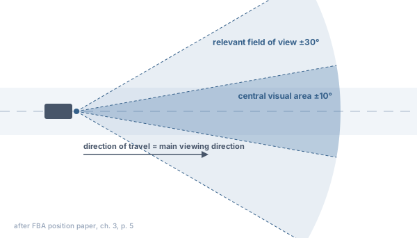
Situations in which disturbing glare can occur:
- carriageways running parallel or oblique to a system, with the low sun in the direction of the road,
- systems directly beside the carriageway that cast reflections flat along the road,
- bends in which the viewing direction deviates from the momentary path,
- acceleration lanes, slip roads, junctions and intersections with side and shoulder glances,
- truck drivers who sit higher than car drivers and can see over screens,
- bridges, embankments and cuttings that change the eye height relative to the terrain,
- tracking systems in stow, fault or special positions.
VI.2.2 Guidelines at a glance
| FBA position paper (Germany) | OVE R 11-3 (Austria) | RVS 05.06.11 (Austria) | |
|---|---|---|---|
| Edition, status | as of November 2025, update announced; plus "Required documents", as of January 2025 | edition 01.11.2016; withdrawn as of 01.12.2024, unofficially often still applied for orientation | leaflet, edition 01.12.2011; covers information and advertising signs, not PV |
| Scope | PV systems at federal trunk roads; other roads not covered | traffic routes in general | drivers on roads |
| Relevant field of view | ±30° around the main viewing direction; extended at merges, on- and off-ramps | cone of about 30° to the main viewing direction | 30° visual cone (half or full angle not specified) |
| Central visual area | ±10° | not specified | not specified |
| Luminance | not significant at ≤ 30,000 cd/m² | no threshold | no value for reflections |
| Size of the source | not significant at vertical size ≤ 0.30° outside ±10° | not specified | not specified |
| Sun overlap | only at sun elevation ≤ 5°; no angle given | not specified for traffic | not specified |
| Illuminance | named as an intensity quantity, without threshold | not specified | ≤ 1 lx for illuminated signs in the visual cone |
| Duration | no limit; duration and periods are to be shown | no time threshold for traffic | not specified |
| Eye height | car 1.0 m, truck at least 2.7 m above road surface | not specified | truck approx. 2.5 to 3.0 m |
| Time resolution | at most 5 min, whole year | not specified | not specified |
| Module | module-typical reflection with beam spread | no separate specification for traffic | not specified |
| Occlusion | permanent obstacles only; roadside greenery does not count | not specified | not specified |
| Special locations | merges, on- and off-ramps, traffic control systems | glare at junctions, crossings, accident black spots and weaving sections not permitted | not specified |
References are given in sections VI.2.3 to VI.2.5. The Swiss guide of EnergieSchweiz/Swissolar contains no rules for roads.
The position paper applies to glare reports and expert statements in permit procedures for PV systems along federal trunk roads (position paper, chap. 1, p. 3). For state, district and municipal roads, none of the sources evaluated here contains requirements of its own; whether the position paper is applied by analogy is decided by the user.
Not regulated in any source: a vertical field of view, the spacing of observation points along the route, vehicle geometry (sun visor, roof edge, A-pillar; apart from the reference to the visor) and a reduction due to cloud cover. Railways are not covered by the position paper (Ch. VI.3).
VI.2.3 Position paper of the Federal Highway Authority (Germany)
Occasion and protection zones. For PV systems on components of federal trunk roads and within the protection zones of § 9 FStrG (Federal Trunk Roads Act), the effects on the safety and ease of traffic must be considered (chap. 1, p. 2). According to the application notes, the building prohibition zone extends 40 m (motorways) or 20 m (federal roads under federal administration) and the building restriction zone 100 m or 40 m, each measured from the outer edge of the paved carriageway (required documents, p. 1).
When an assessment is needed (chap. 2, pp. 3–4). An assessment is required for all systems that can be seen, or potentially seen, by road users on federal trunk roads. A glare report may be requested if reflections towards the carriageway are possible, the system lies within sight, or topography or module height may lead to impairment. An expert statement suffices if permanent obstacles (such as noise barriers or embankments) interrupt all lines of sight to all parts of the system, or if the module fronts are not visible because of topography or orientation. Roadside vegetation does not count as a permanent obstacle because it is maintained and its screening is not reliable. The application notes also disregard existing vegetation as glare protection in principle; dense and permanent vegetation such as forests may be suitable (required documents, p. 2).
Initial hypothesis (chap. 3, p. 5). Glare effects cannot be ruled out if, taking all sun positions of a year into account, reflections occur within the relevant field of view of ±30° around the main viewing direction. The luminance of standard modules with a lightly structured surface and anti-reflective coating is as a rule far above 100,000 cd/m²; reflections are therefore to be regarded as relevant in the first step. On straight sections it can be assumed that the main viewing direction follows the course of the road. Where there is an increased need to look around, the assumption must be extended: at acceleration lanes and merges (side glances at the merging lane), at slip roads and in other complex situations, for example in the area of traffic control systems (pp. 5–6). The application notes require a viewing angle of at least ±30° in the viewing direction (required documents, p. 2).
Exclusion of relevant glare effects (chap. 3, p. 6). A reflection within the relevant field of view can be classified as not significantly impairing if one of the following applies:
| Criterion | Content |
|---|---|
| luminance | reflecting surface with ≤ 30,000 cd/m² |
| size of the source | vertical size of the glare source in the field of view outside the central visual area (±10°) ≤ 0.30° |
| sun overlap | the sun overlaps the glare effect; since sun glare can as a rule be reduced by the vehicle's visor, only at very low sun positions (elevation ≤ 5°) |
| angular distance and intensity | reflections within the relevant visual area that, owing to their angular distance from the main viewing direction and their intensity, do not cause relevant glare |
| further aspects | possible, but to be presented plausibly and soundly |
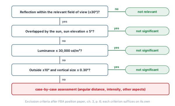
For sun overlap, the position paper gives only the sun elevation, not an angle between sun and reflection.
Requirements for the calculation (chap. 4, pp. 6–7):
- consideration of the whole year at a time resolution of at least 5 minutes,
- determination of the angle at which reflections enter the driver's field of view,
- determination of the reflection intensity (for example illuminance near the eye, luminance) for reflections within the relevant field of view,
- calculation with standard values or with proven module-specific reflection properties; module-typical reflections including beam spread must be taken into account,
- reflection directions and times from module tilt and orientation; the influence of cross tilts resulting from slopes on the PV area must be taken into account and presented,
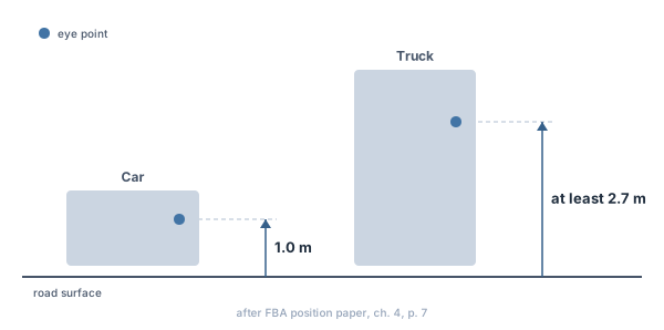
- observation points with eye heights above the road surface: car 1.0 m, truck at least 2.7 m; sufficiently precise elevation data.
As results the paper requires the angular ranges in the field of view with reflections, duration and periods of the reflections per observation point and, if reflections occur within the relevant field of view, a detailed assessment (p. 7).
Tracking systems (p. 9): to be considered are proper tracking including backtracking as well as stow, fault and special positions (for example for vegetation maintenance or agricultural use).
Mitigation (chap. 5, p. 8): structural measures such as interrupting lines of sight or changing module orientation, adapted tracking strategy or stow position, glare protection measures including low-glare modules with a luminance of the reflections in the relevant field of view of ≤ 30,000 cd/m² at all sun positions. Measures on the federal trunk roads and their components are not permitted.
VI.2.4 OVE R 11-3 (Austria)
For drivers, a cone of about 30° to the main viewing direction is particularly important; reflections transverse to the direction of travel do not impair visual performance but can distract (section 4.2, pp. 9–10). With reference to RVS 05.06.12, glare is not permitted at intersections, crossings, accident black spots, weaving sections and places with speed differences; if it nevertheless occurs, the planning must be changed or a traffic engineering expert consulted (section 6.2.1, p. 12; section 7.2, p. 13). The guideline has been formally withdrawn but in Austria is unofficially often still applied for orientation (see Ch. VI.1).
VI.2.5 RVS 05.06.11 (Austria)
The information sheet regulates the locations of information and advertising media and their light; it does not mention photovoltaics. It states that sunlight combined with mirroring surfaces can cause glare effects similar to light sources and leaves the measure to the individual case (section 5.1, p. 13). The following reference values are transferable:
- 30° sight cone: reference space for assessing drivers (section 4.2, p. 7, and other places). The information sheet does not state whether the 30° is meant as a half or full opening angle.
- Glare illuminance: a lit information medium is permitted within the 30° sight cone if it does not exceed a glare illuminance of 1 lx; above that, a lighting assessment is required (section 5.1, p. 13). For sports lighting the sheet limits the vertical illuminance to 1 lx inside and 10 lx outside the 30° sight cone; 1 lx corresponds approximately to oncoming vehicles with correctly adjusted headlights (section 6.7, p. 20).
- Eye height: truck drivers with an eye height of approx. 2.5 to 3.0 m (section 4.3, p. 8); ground-level field of view of a driver up to 3.0 m height (section 4.1, p. 7).
VI.2.6 Settings in PV-GlareCheck
Note on application. The following settings are conceivable interpretations and examples of application of the guidelines, not a binding implementation. Which guideline applies and how it is correctly interpreted and applied in the individual case must be verified independently by the user.
VI.2.6.1 Editor
| Setting | FBA position paper | OVE R 11-3 / RVS | Chapter |
|---|---|---|---|
| Module type of the PV areas | real module type with measured profile (beam spread); not "Perfect mirror" | not specified | Ch. 8 |
| Observation points | "Points along a line" per lane and direction of travel; denser at bends, junctions and acceleration lanes | as FBA; include junctions, crossings and weaving sections | Ch. 9 |
| "Height a. GL" | car 1.0 m, truck 2.7 m; on bridges set GL manually | truck 2.5 to 3.0 m (RVS) | Ch. 9 |
| Field of view | "Enable and align fields of view along the line"; "H±" 30° | cone of about 30°; can be modelled as ±30° or ±15° | Ch. 9 |
| Occlusion | noise barriers, embankments, structures as obstacles, no roadside greenery; terrain via terrain occlusion | not specified | Ch. 10, Ch. 6 |
| Cross tilt | account for and show the slope of the area | – | Ch. 7.6 |
| Tracking systems | backtracking with "Rest Angle"; stow, fault and special positions only as a fixed tilt in a separate version | – | Ch. 7.3, Ch. 13 |
VI.2.6.2 Possible filter combinations
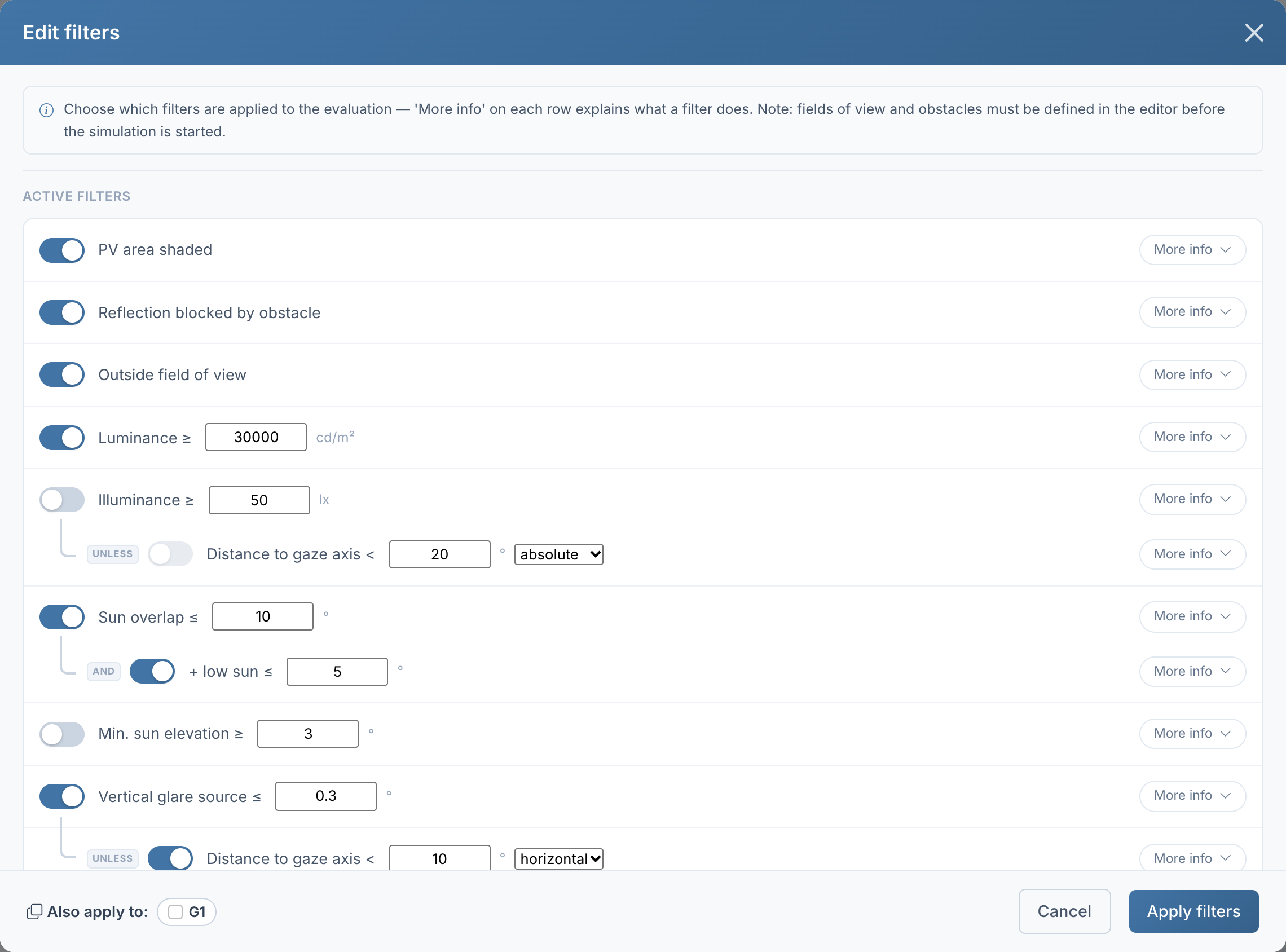
The table shows one possible filter combination per guideline. It lists the filters that can be derived from the guideline, and filters that are switched on in a new report and are switched off for it. Further filters (Ch. V.8) can be added at the user's discretion where they are professionally justified. The filters are set per group under "Evaluation method" with "Edit filters" (Ch. 14, Ch. V.8); "Also apply to:" in the dialog transfers them to other groups, "Save as Preset" stores them. No new simulation is needed for this.
| Filter ("Evaluation method") | FBA position paper | Remark |
|---|---|---|
| "PV area shaded" | on | sun on the area occluded |
| "Reflection blocked by obstacle" | on | only permanent obstacles entered |
| "Outside field of view" | on | relevant field of view ±30° |
| "Luminance" ≥ | 30,000 cd/m² | app default; the app removes time steps below the value, the paper treats ≤ 30,000 cd/m² as insignificant; the difference concerns only exactly 30,000 cd/m² |
| "Sun overlap" ≤ | angle freely selectable, often 10° following the LAI | the paper gives no angle |
| "+ low sun ≤" | 5° | sun elevation according to the paper |
| "Vertical glare source" ≤ | 0.3° | |
| "UNLESS" "Distance to gaze axis <" | 10°, axis "horizontal" | central visual area ±10° horizontally; the extent threshold does not apply there |
Explanations:
- "Vertical glare source" evaluates the vertical angular extent β at which the glare source appears. Areas that appear stacked in the same viewing direction form one combined source. With the filter "Outside field of view" switched on, only the parts of the source inside the field of view count.
- The exception "Distance to gaze axis" with the axis "horizontal" checks only the azimuth offset from the gaze axis and thus corresponds to the horizontally defined central visual area. With "absolute" the spatial angle counts; it is never smaller than the horizontal offset, so the exception then applies less often.
- For Austria, "Illuminance" ≥ 1 lx can additionally be set following RVS 05.06.11. The filter evaluates the sum of the visible contributions of all sources in a time step at the observation point. The information sheet sets this value for lighting and advertising installations, not for reflections from PV systems.
VI.2.6.3 Criteria and evaluation quantities
| Quantity in the report | Relation to the position paper |
|---|---|
| "Min. gaze axis distance" with the H and V values | angle at which the reflection enters the field of view; position relative to the central area ±10° |
| "Peak luminance" | comparison with 30,000 cd/m² |
| "Peak illuminance" | intensity at the eye |
| "Total glare duration per year", "Max. daily glare", "Days >0 / >30 / >60 / >120 min glare" | duration of the reflections |
| "Glare times (day × time)", "Daily glare duration" | periods of the reflections |
| "3D Perspective (Azimuth / Elevation)" | angular ranges in the field of view with reflections |
| "Reflection map (top-down)" | reflection directions in plan view; the sketched rays show directions, not necessarily the reflecting region |
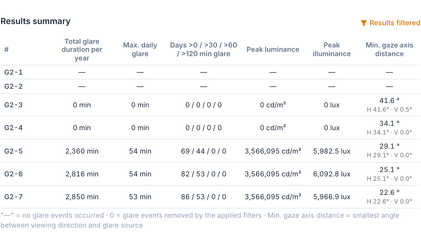
In the group table, "—" means that no reflection occurred at the point, and "0" that reflections occurred but were removed by the active filters. The table does not show which filter took effect. To name the reason for exclusion per point, as the position paper requires, the filters can be switched off and on individually and the results compared.
VI.2.6.4 Example
Ground-mounted system with azimuth 180° and tilt 20°, module type "Standard Module", about 100 m north of a rural road. One group per direction of travel with a truck eye height of 2.7 m, points every 30 m, field of view ±30° in the direction of travel, filters as above. Calculated as a sample project with a fictitious installation.
- Towards the north-east (G1): All reflections lie 133° from the gaze axis, i.e. behind the driver. Result: 0 min.
- Towards the south-west (G2): At G2-5 to G2-7, reflections occur within the field of view, 22.6° to 29.1° from the gaze axis and therefore outside the central area of ±10°. Luminance and vertical size are above the thresholds. None of the filters set removes these reflections. The report shows duration and time of day: up to 54 min per day, around 18:00 in April and in August (Ch. 14).
VI.2.7 Notes
VI.2.7.1 Narrowing down relevant road sections
The Pre-analysis ("Reflection Pre-Analysis", Ch. 11) shows which sections of a road lie within the possible reflection area. Sections outside it can be covered with few points; sections inside it, especially bends, junctions and acceleration lanes, with more closely spaced points.
VI.2.7.2 Groups and points along the carriageway
Observation points (Observation point, Ch. 9) belong to groups; the report filters and evaluates per group. For roads, one group per road, direction of travel and vehicle type can be created.
- Create a "New group" and name it after road, direction of travel and vehicle type.
- Choose "Points along a line" and enter the "Distance between points" (10 m to 1,000 m). "Always end line with a point" places a point at the end of the line even if the distance there is shorter.
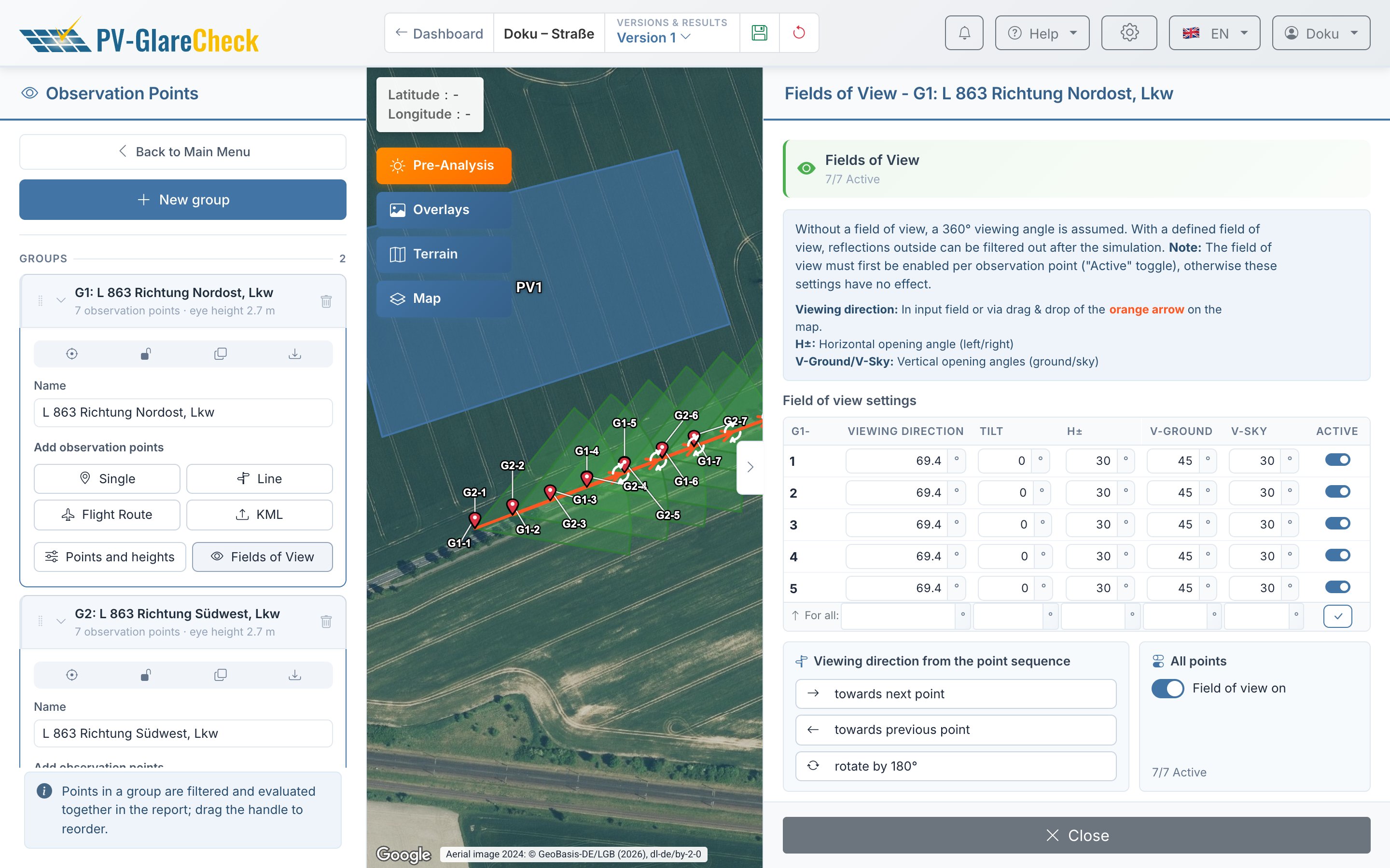
- Turn on "Enable and align fields of view along the line" and under "Viewing direction" choose "Along drawing direction" or "Against drawing direction". The line is drawn on the lane of the direction under consideration. Each point receives an active field of view with the direction of the line segment, "Tilt" 0°, "H±" 30°, "V-Sky" 30° and "V-Ground" 30°.
- For the opposite direction, the group can be copied with "Duplicate group" and reversed in the "Fields of View" menu with "rotate by 180°". On dual carriageways the points of the opposite direction lie on its own lane; a separate line is drawn for it.
- For cars and trucks, the group can likewise be duplicated and the eye height set in "Points and heights" with "For all:" (field "Height"): according to the position paper 1.0 m (car) and at least 2.7 m (truck) above the road surface.
Height reference. The app takes the Ground level from the elevation data (Ch. 6) and adds the eye height to it. The position paper refers the eye height to the road surface. On bridges, a terrain model usually provides the ground beneath the structure; jumps in GL between neighbouring points in "Points and heights" indicate this. There, "Calculate GL automatically" can be switched off and the carriageway height entered by hand.
VI.2.7.3 Field of view per traffic situation
The field of view (Field of view / FOV, Ch. V.6) is a window around the gaze axis with the half horizontal opening angle "H±" and the vertical angles "V-Sky" and "V-Ground"; "Tilt" tilts the gaze axis.
| Situation | Modelling in the "Fields of View" menu |
|---|---|
| straight section | "Viewing Direction" = direction of travel, "H±" 30° (position paper, application notes) |
| bend | The main viewing direction looks ahead along the bend. "Viewing direction from the point sequence" with "towards next point" aligns each point towards the next point of the group; the larger the point spacing, the further the axis looks into the bend. Alternatively, "Viewing Direction" is set by hand per point. |
| acceleration lane, junction, slip road | widen "H±" or place a second point with a sideways direction; the position paper gives no figure for the extension |
| Austria (OVE, RVS) | cone of about 30° to the main viewing direction; whether the half or full opening angle is meant is not defined: "H±" 30° or 15° |
The vertical angles are not defined in any source. The values "V-Sky" and "V-Ground" are entered explicitly per point; the report shows them per point under "FOV parameters".
VI.2.7.4 Occlusion
Noise barriers, embankments, structures and earth walls can be entered as an Obstacle (Ch. 10.1), terrain ridges and cuttings via Terrain occlusion (Ch. 6). According to the position paper, roadside vegetation does not count as a permanent obstacle. If vegetation is nevertheless entered, for example for a variant, a version without these obstacles can additionally be calculated (Ch. 13).
VI.2.7.5 PV areas and module type
- Cross tilt: the position paper requires cross tilts resulting from the slope of the area to be taken into account and presented. This can be modelled via the Cross tilt of the PV area (Ch. 7.6); the report presents it in the appendix.
- Tracking systems: tracking with backtracking and "Rest Angle" (minimum angle during backtracking) are set on the PV area (Ch. 7.3). Tracking has no separate operating mode for stow, fault or special positions; such a position can be calculated as a fixed tilt in a separate version (Ch. 13).
- Module type: the position paper requires module-typical reflections including beam spread. This can be modelled with a module type that has a measured Module profile (Ch. 8). The module type "Perfect mirror" calculates without beam spread and with the luminance of the sun; the luminance criterion would then be meaningless. Low-glare modules can be calculated with the reflection profile according to the manufacturer's data, provided it has been created in the module catalogue.
VI.2.7.6 Simulation
The app calculates a whole year in time steps of 1 min with a cloudless sky (Ch. 12, Ch. V.1); the requirement of a resolution of at least 5 min is thus covered.
VI.2.7.7 Literature on the visual field
Jurado-Piña and Mayora (2009) cite that 80 % of drivers' fixations lie within the central 15° of the visual field and derive glare cones of 19° (40-year-old drivers) and 25° (60-year-old drivers) around the gaze axis for direct sun glare (Transportation Research Record 2120, p. 13). The values refer to the sun, not to PV reflections; they support grading by angular distance to the gaze axis.
VI.2.7.8 Limits of the modelling
- Moving observer: each observation point is fixed. The duration at a point is not the time for which a passing driver sees a reflection. The quantity "period for which the same angular distance persists along the route" (position paper, p. 5) is not reported directly; it can be estimated from dense rows of points.
- Static viewing direction: the field of view is fixed per point. Side and shoulder glances are captured only through a widened or additional field of view.
- Rectangular field of view: the field of view is a rectangle in azimuth and elevation, not a cone.
- Vehicle: sun visor, roof edge, A-pillar and windscreen are not modelled. The condition "+ low sun ≤" represents the position paper's reasoning (sun visor) only via the sun elevation.
- Sun overlap with extended sources: the angle α is formed per time step and PV area as the mean over the reflecting regions.
- Elevation data: bridges, embankments and cuttings are only as accurate as the elevation data; the GL on structures is set by hand.
- Vegetation: obstacles act identically all year; maintenance and foliage are not modelled.
- Real reflection: luminance and extent depend on the module profile. For low-glare surfaces the position paper requires proof of the reflection behaviour for all relevant angles of incidence and for the interaction of the modules (chap. 2, p. 4); the simulation does not replace this proof.
VI.2.7.9 Settings in the report
The report itself documents the settings used (Ch. 14):
- the filters per group as filter cards under "Evaluation method",
- for each observation point the position, terrain height, observer height and, where applicable, the field of view in the chapter "Observation Points",
- in the appendix module types with their characteristic curves, elevation data sources and simulation parameters, where applicable also the differentiated cross tilt,
- version and calculation state on the cover page.
The report does not show which filter took effect at a point (section VI.2.6.3). Measures and variants, for example a calculation without vegetation as an obstacle, are created as separate versions with their own report (Ch. 13).
VI.2.8 Sources
- Fernstraßen-Bundesamt: Eckpunktepapier Photovoltaik – Blendwirkungen und Blendgutachten, as of November 2025.
- Fernstraßen-Bundesamt: Erforderliche Unterlagen bei der Errichtung von Photovoltaikanlagen in den Nahbereichen der Bundesfernstraßen, as of January 2025.
- Österreichische Forschungsgesellschaft Straße – Schiene – Verkehr (FSV): RVS 05.06.11 Visuelle Störwirkungen – Kriterien zu Standorten von Informationsträgern, information sheet, edition 1 Dec 2011.
- OVE: OVE-Richtlinie R 11-3 "Blendung durch Photovoltaikanlagen", edition 2016-11-01 (withdrawn 2024-12-01).
- Jurado-Piña, R.; Pardillo Mayora, J. M.: Methodology to Predict Driver Vision Impairment Situations Caused by Sun Glare. Transportation Research Record 2120 (2009), pp. 12–17.
See also
- Ch. 9 Observation points
- Ch. 7.3 Orientation and mounting (fixed, east-west, tracker)
- Ch. 7.6 Cross tilt
- Ch. 10.1 Obstacles
- Ch. 13 Variants: batch, version comparison, worst case
- Ch. 14 Report
- Ch. V.6 Is the reflection within the field of view?
- Ch. V.8 Filters
- Ch. VI.1 Residents
- Ch. VI.3 Rail traffic
- Ch. VI.4 Air traffic