
In brief
The same procedure applies to all protected interests: use the pre-analysis to narrow down where the system reflects, place observation points with the appropriate tool, choose height, field of view and module type according to the guideline, and set the filters per group in the report.
VI.5.1 Assessment procedure
- Collect documents. Location and orientation of the PV areas, data sheet or measurement report of the module, location of the sensitive places, for traffic routes the alignments, for aerodromes approach charts and threshold elevations.
- Narrow down reflection directions. In the pre-analysis, the cones show which buildings, roads or flight paths lie in a reflection direction (Ch. 11). If observers are higher than the system, for example on an upper floor or on approach, "Max" of the angle filter can be increased.
- Place observation points with the tool that fits the situation (VI.5.2).
- Height, field of view and module type according to the guideline (VI.5.3).
- Occlusion: enter it as far as it is documented (VI.5.4).
- Simulate and set the filters per group in the report according to the assessment basis (VI.5.5).
- Check results (VI.5.6); the report shows the settings used (VI.5.7).
VI.5.2 Tools for observation points
| Situation | Tool | Note |
|---|---|---|
| Window, balcony, terrace | "Place single points" | one point per protected room or outdoor area, one group per floor (Ch. VI.1) |
| Undeveloped building plot | "Place single points" or "Points along a line" along the edge | at the most affected edge (Ch. VI.1) |
| Road, path | "Points along a line" with "Enable and align fields of view along the line" | one group per direction of travel; opposite direction as a copy with "rotate by 180°" (Ch. VI.2) |
| Railway line | "Points along a line" as for roads | one group per direction of travel; denser before signals and level crossings (Ch. VI.3) |
| Approach, departure, traffic circuit | "Flight Route" (Pro) | height linear between start and end point (Ch. VI.4) |
| Taxiway | "Points along a line" | cockpit eye height above ground (Ch. VI.4) |
| Control tower | "Place single points" | controllers' eye height above ground (Ch. VI.4) |
| Points from GIS or Google Earth | "Import points from KML" | replaces all existing points of the group (Ch. 9) |
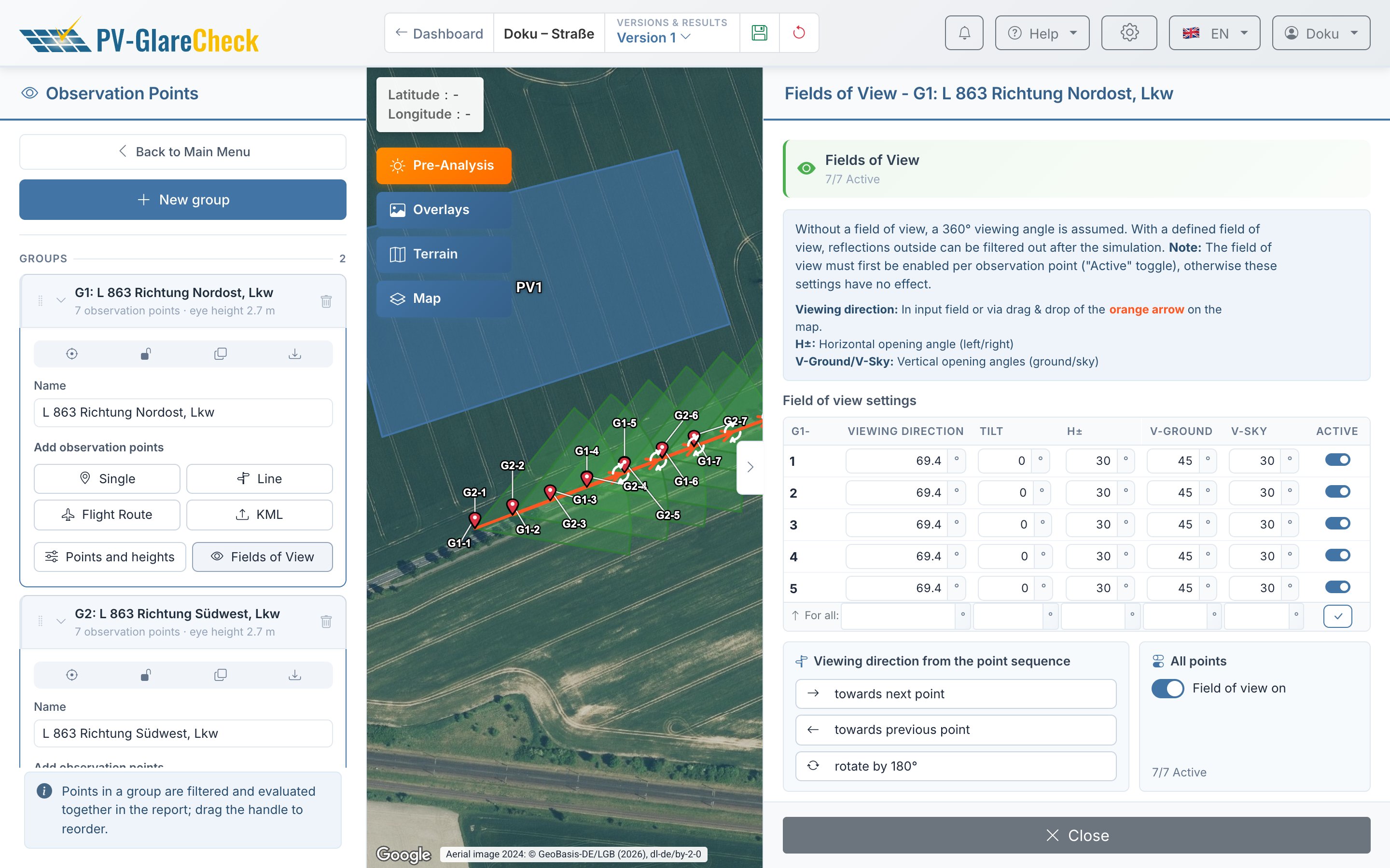
Groups are the unit of assessment: the report filters and evaluates per group (group). A group therefore contains only points that are assessed on the same basis and with the same assumptions, for example one floor, one direction of travel with one vehicle type, or one approach path. Variants of the same row of points, such as car and truck, are created with the "Duplicate group" button on the group card and a different height.
Point spacing. None of the sources evaluated specifies a spacing. It is chosen so that the points resolve the course of the reflections: denser in bends, at junctions and where the pre-analysis shows reflections; wider in sections without a reflection direction. "Points along a line" allows 10 m to 1,000 m.
Number. Up to 30 points in the Free plan and 100 in the Pro plan, across all groups of the project (Ch. 3). Points may lie outside the project area.
VI.5.3 Height, field of view and module type per protected interest
Note on application. The table summarizes the settings from VI.1 to VI.4. They are conceivable interpretations and examples of application of the guidelines, not a binding implementation. Which guideline applies and how it is correctly interpreted and applied in the individual case must be verified independently by the user.
| Protected interest | "Height a. GL" | Field of view | Module type | Chapter |
|---|---|---|---|---|
| Residents, LAI and OVE | eye height per floor; undeveloped area 2 m (LAI) or possible building height (OVE) | none | "Perfect mirror" | Ch. VI.1 |
| Residents, Swissolar | eye height per floor | window normal, H±, V-Ground, V-Sky 70° each (approximation) | duration: "Perfect mirror"; luminance: real module type | Ch. VI.1 |
| Road | car 1.0 m, truck 2.7 m | in direction of travel, H± 30° | real module type | Ch. VI.2 |
| Railway | approx. 2.5 m above top of rail (rough guide value) | in direction of travel, H± 30° | real module type | Ch. VI.3 |
| Approach | flight altitude from the glide path | in flight direction, tilt = glide angle, H± 50° | real module type | Ch. VI.4 |
| Control tower | controllers' eye height | none (FAA) or towards the runway (EASA) | real module type | Ch. VI.4 |
- GL comes from the elevation data. On bridges, embankments and floor slabs, this is the ground below; there, "Calculate GL automatically" can be switched off and the height entered manually (Ch. 9).
- Fields of view do not restrict the calculation: the simulation calculates all reflections and records for each one whether it lies outside the field of view; the report excludes these via the "Outside field of view" filter (Ch. V.6). Because this record is stored with the result, a changed field of view only takes effect in a new simulation.
- Real module type means the reflection profile from the data sheet or measurement report of the module to be installed in the project. An entry in the module catalog is only used if it is based on the same document (Ch. 8). If a profile is missing, another module type does not represent the module.
VI.5.4 Occlusion
- Buildings, walls, embankments, noise barriers are entered as obstacles (Ch. 10.1), with height from plans, surveys or official building models.
- Terrain between system and observer and around the system is captured by terrain occlusion from a terrain model (Ch. 6): it blocks reflections and shades the PV areas. Distant mountains are captured by far-field shading (Ch. 10.2).
- Vegetation changes over time. The FBA position paper does not accept roadside greenery as a screen (Ch. VI.2). If vegetation is entered as an obstacle, it acts identically all year (Ch. VII).
- The effect of an occlusion can be shown as a variant alongside a calculation without occlusion (Ch. 13).
VI.5.5 Possible filter combinations
For each guideline, sections VI.1 to VI.4 show one possible filter combination; the table points to them. Further filters can be added at the user's discretion where they are professionally justified. The simulation stores all geometrically possible reflections; the filters determine what counts as glare (Ch. 14, Ch. V.8). They are set per group and take effect immediately, without a new simulation.
| Assessment basis | Filter table |
|---|---|
| LAI, OVE R 11-3, Swissolar | Ch. VI.1, section VI.1.6.2 |
| FBA position paper, OVE, RVS | Ch. VI.2, section VI.2.6.2 |
| Railway (FBA position paper by analogy) | Ch. VI.3, section VI.3.5.2 |
| EASA, FAA | Ch. VI.4, section VI.4.6.7 |
- A new report is already filtered, among other things with "Luminance ≥ 30,000 cd/m²". In the possible combinations for LAI, OVE and the FAA this filter is off; for EASA it is set to 20,000 cd/m².
- "Save as Preset" keeps a setting for all of your own reports, for example one preset per guideline. "Also apply to:" in the dialog transfers it to further groups.
- The filter card at the start of each group documents the setting in the PDF.
VI.5.6 Checking results
- Distinguish "—" and "0": "—" means that no reflection occurred at the point; "0" means that reflections occurred but were filtered out. Which filter took effect becomes apparent when the filters are switched off and on again individually.
- Cross-check directions: the "Reflection map (top-down)" must match the cones of the pre-analysis; the "3D Perspective" shows where in the field of view the glare source lies and how close it is to the sun.
- Cross-check times: glare in the evening comes from areas that direct the low western sunlight towards the observer, glare in the morning correspondingly from the east. All times are standard time without daylight saving time.
- Compare variants: a different orientation, a different module type or a screen can be compared as a batch analysis or in the version comparison (Ch. 13).
- Maximum values: all values apply to a cloudless sky on every day (Ch. VII).
VI.5.7 Settings in the report
The report itself documents the settings used (Ch. 14):
- the filters per group as filter cards under "Evaluation method",
- for each observation point the position, terrain height, observer height and, where applicable, the field of view in the chapter "Observation Points",
- in the appendix geodata, module types with their characteristic curves, elevation data sources, simulation parameters, assumptions and glossary,
- version and calculation state on the cover page.
Variants, for example with a different module type or with and without occlusion, are created as separate versions with their own report (Ch. 13).