
In brief
Glare only occurs if the sun reaches the module surface and the reflection reaches the observer. Both can be interrupted: by a building, a row of trees, a hill or a mountain ridge. For this, the app represents drawn obstacles, the terrain from terrain models, far-field shading via a horizon line, and the body of the PV area itself.
Overview
Two paths are checked. Which path a kind acts on also decides under which report filter a blocked reflection appears (Ch. V.8).
| Occlusion | Sun → PV area | PV area → observation point | Basis | Section |
|---|---|---|---|---|
| drawn obstacles | yes | yes | polylines with height above ground | 10.1 |
| far-field shading | yes | no | horizon line per PV area (PVGIS) | 10.2 |
| terrain occlusion | yes | yes | terrain models in the project | 10.3 |
| body of the PV area | no | only parts of the same area | elevation grid or roof plane, bottom and top edge | 10.4 |
| topography obstacles (deprecated) | yes | yes | drawn terrain ridges from older projects | 10.5 |
| Report filter | "PV area shaded" | "Reflection blocked by obstacle" | both on by default |
Blocked reflections are flagged, not deleted; with the filter switched off they count again (Ch. V.4).
10.1 Obstacles
- In the "Obstacles" menu, click "New obstacle" and choose "Draw on Map" or "Upload KML File" (lines and polygons; each geometry becomes a separate obstacle).
-
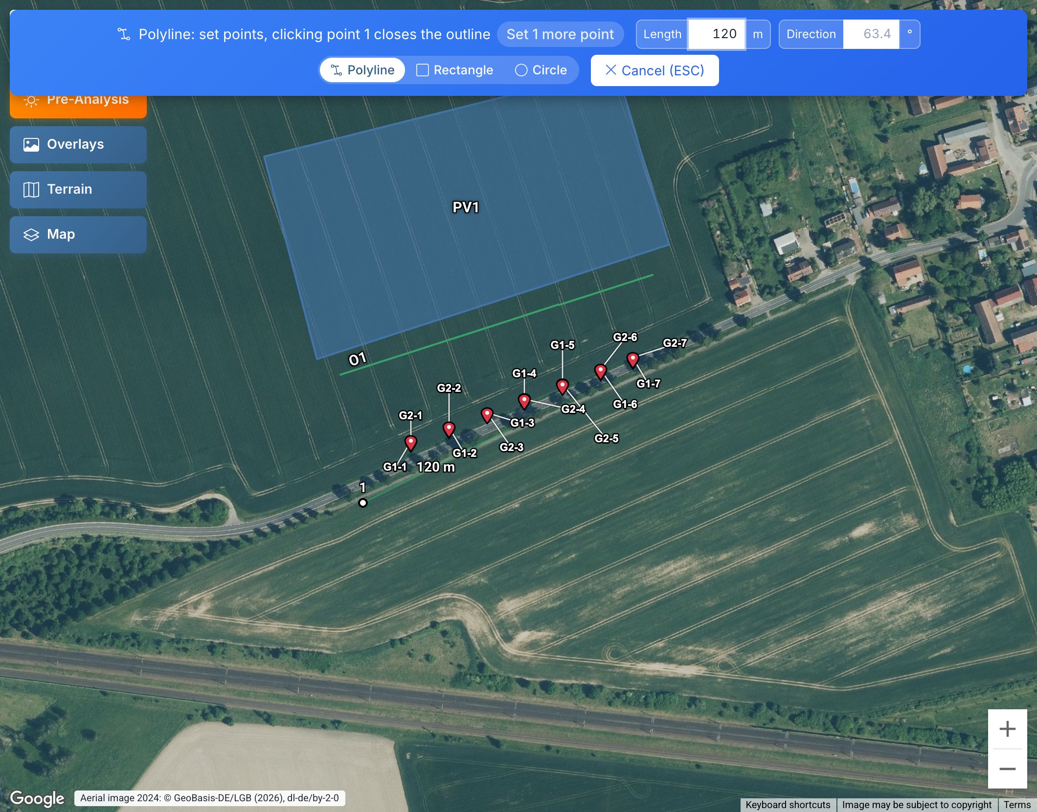
When drawing, choose the shape above the map:
- Polyline: set points; "Click here or double-click to finish" ends the input from two points on, clicking point 1 closes the outline.
- Rectangle: click two corners of one edge, then the depth.
- Circle: click the centre, then the radius; the result is a polygon with 16 corners.
Exact values. Instead of clicking, the dimensions can be entered in the blue drawing banner: for a polyline the "Length" and "Direction" of the next edge, for a rectangle first the length and direction of the edge, then the "Depth", for a circle the "Radius". The fields show the value at the mouse in grey. Typing a number jumps into the first field, Tab switches the field, Enter places the point; an empty field takes the value at the mouse, Esc cancels. The direction is in degrees from north, clockwise (90 = east); length, depth and radius are at least 0.5 m. The mouse decides on which side of the edge the depth lies. 3. In the detail view under "Coordinates and Heights", enter the height above ground per point; the initial value is 10 m. "For all:" applies one value to all points. 4. With "Calculate GL automatically" switched on, the GL comes from the elevation data (Ch. 6).
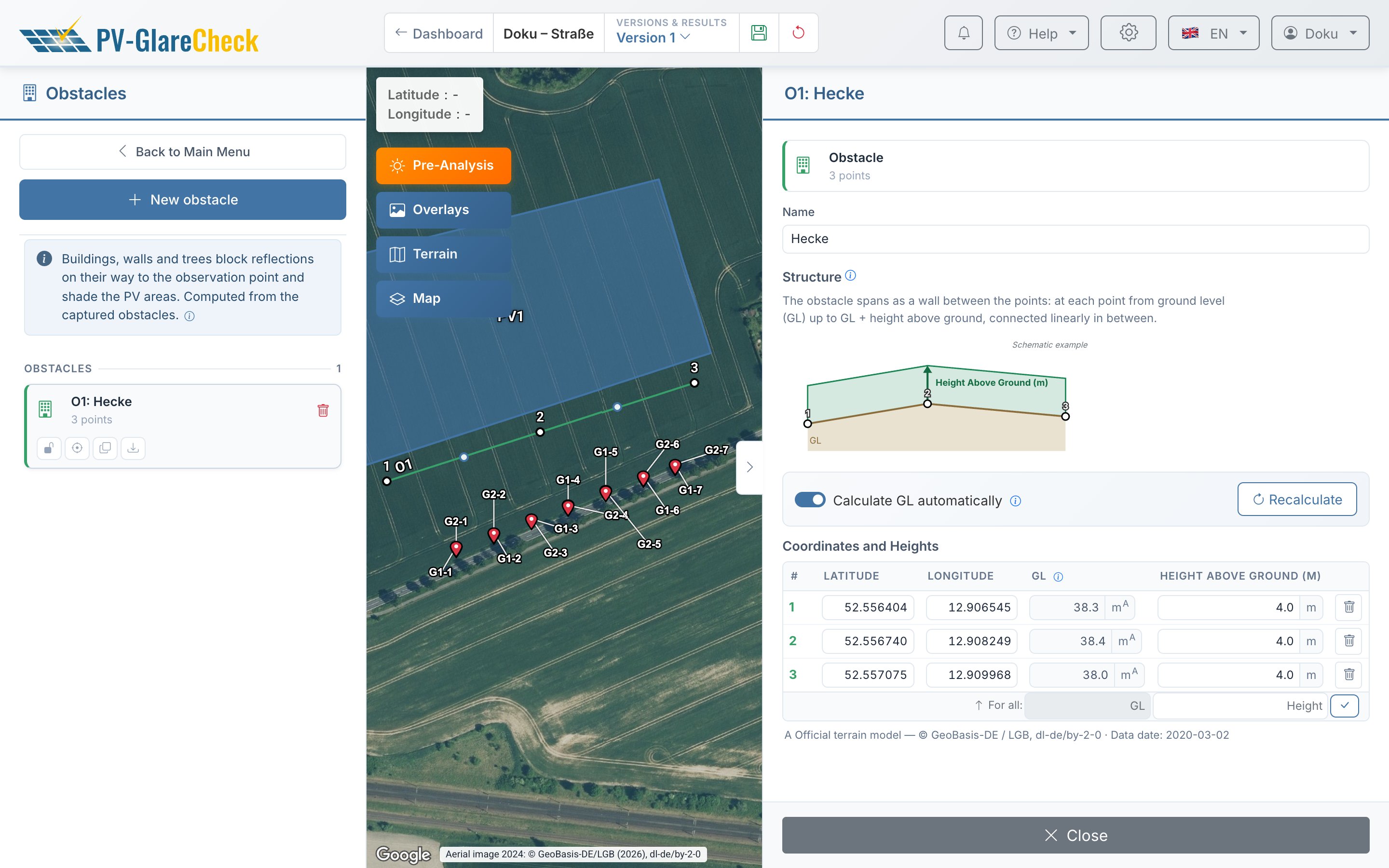
Effect. An obstacle is a polyline. Between each pair of points, a vertical wall is created from GL up to GL plus height above ground; rays above and below this band stay free. A closed outline is created if the last point lies on the first or a KML polygon is imported. Both paths are checked, sun → PV area and PV area → observation point. A reflection is only blocked if the obstacle lies closer to the observation point than the reflecting point.
An obstacle has no lid: anyone looking over the wall at the PV area sees the reflection. For a building, the outline with the ridge height is therefore enough; there is no roof as a surface. No terrain model contains buildings and vegetation, so they are always entered as obstacles; obstacles apply in addition to terrain occlusion (section 10.3).
Points to note
- Number: up to 10 obstacles in the Free plan, 100 in the Pro plan per simulation run.
- GL missing: If fetching the elevation fails at a point, its GL stays empty; without GL at all points, no simulation starts.
- KML import rejects the whole file if a polygon has holes, a geometry has too few points or the plan limit is exceeded.
Details: check, GL by hand, report
Check. Sun → PV area: for each hit cell, a ray from its centroid towards the sun is intersected with all walls. PV area → observation point: a wall blocks a point if it covers its elevation angle and lies closer to the observation point than the point; a cell counts as blocked if more than half of its points are blocked (Ch. V.4).
GL by hand. With "Calculate GL automatically" switched off, an entered value is kept even when the point is moved; switching it on again fetches all values anew.
Report. The "Obstacles" chapter lists for each obstacle the type, number of points, terrain elevation and, for above-ground obstacles, height above ground and top edge; the appendix shows a map and a point table with source markers (Ch. 14).
10.2 Far-field shading
The horizon line gives, per compass direction, up to which elevation angle distant terrain hides the sky. It acts only on the path sun → PV area; it does not block lines of sight to the observation point. Available in every plan.
- Open the "Far-field shading (horizon)" menu.
- Under "Horizon per PV area", click "Enable" for an area, or "Enable for all PV areas".
- In the diagram, check where the sun paths (summer and winter solstice, equinox) lie below the horizon line: there the sun is behind the horizon on that day.
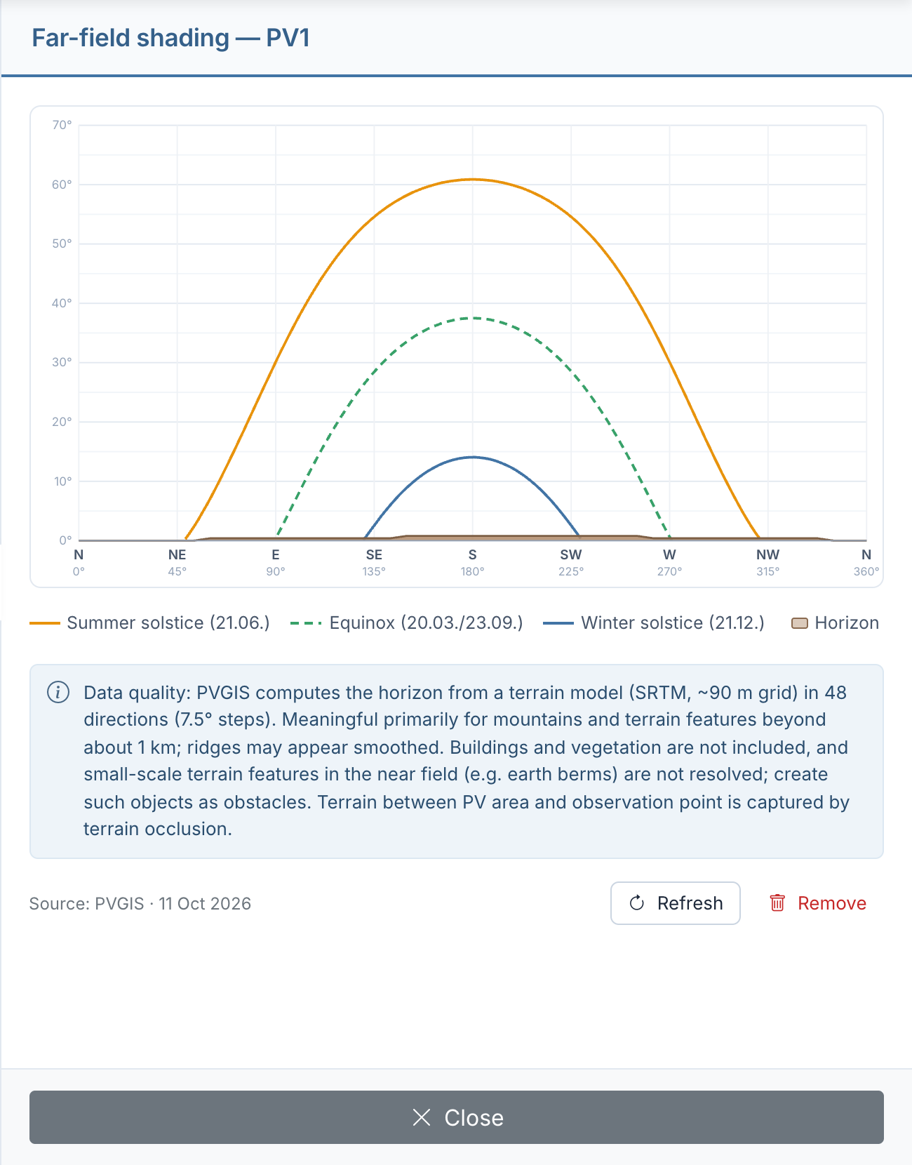
In the example the terrain is flat; the horizon reaches at most 0.8° and practically never shades the area. On slopes and in mountains, the line often cuts the winter sun path considerably.
Data basis. The line comes from PVGIS (Joint Research Centre of the European Commission): terrain model with about 90 m resolution, 48 directions at 7.5° intervals, fetched at the center of the corner points of the PV area.
Effect. If the sun in its direction is on or below the line, the whole PV area counts as shaded in that time step (Ch. V.4); with dual orientation this applies to both halves. These reflections are flagged, not discarded. The report filter "PV area shaded" (on by default) removes them from the evaluation, together with sun shading by obstacles (Ch. V.8). A purely astronomical evaluation in the sense of the LAI guidance (astronomically maximum possible periods) is obtained without horizon lines or with the filter switched off (Ch. VI.1).
Points to note
- Area moved or reshaped: The line belongs to the location where it was fetched; "Refresh" updates it at the new center point.
- The simulation calculates with the line stored at the start. The report shows this line, not the current state in the editor.
- Large areas: The line applies to the center point. If a ridge shades only part of the area, splitting it into several PV areas represents this more accurately.
- Nearby terrain is resolved only coarsely by the line (a 7.5° sector is about 130 m wide at 1 km distance); it does not contain buildings and vegetation.
- The pre-analysis does not take far-field shading into account (Ch. 11).
10.3 Terrain from terrain models
Via terrain occlusion, hilltops, embankments and slopes block reflections between PV area and observation point and shade the PV areas. It is based on the terrain models in the project: loaded from official sources or as a custom file (Ch. 6, section 6.5).
- In the "Elevation data" menu, load or enable a terrain model that covers the stretch between observation points and PV areas and the terrain around the PV areas.
- In the "Terrain occlusion" menu, check the switch. Without an explicit choice it is on as soon as a terrain model is enabled.
Effect. At the start, the app calculates a near horizon from the model for each observation point and stores it with the job. Terrain that lies closer than the reflecting point and reaches its elevation angle blocks; terrain behind the PV area does not. In the report this falls under the filter "Reflection blocked by obstacle"; the 3D perspective shows the terrain as a separate silhouette. For each PV area, the app also calculates at sampling points above the area where terrain up to 2 km away hides the sun; these cells fall under the filter "PV area shaded". Distant mountains are captured by far-field shading (section 10.2), buildings and vegetation by obstacles (section 10.1).
Calculation, range and handling of gaps: Ch. 6, section 6.6, and Ch. V.4.
10.4 Body of the PV area and elevation grid
The app calculates ground-mounted systems and elevated roof systems as a closed body: module surface on top, a side band from the bottom to the top edge, below it a base down to the ground or to the roof surface (Ch. V.2). Roof-parallel areas and facades have no body.
| System type | what the body stands on |
|---|---|
| ground-mounted | on the elevation grid or the best-fit plane from step 1 of the terrain menu (Ch. 7.5) |
| elevated roof system | on the roof plane through the roof heights of the corner points; no elevation grid is needed, a roof that is not flat is entered as several roof areas |
Effect. Base and underside do not reflect but block what lies behind them. This applies only within the same PV area: if an observation point looks at an area from below or from the side, its base blocks the parts of its module surface behind it. The 3D perspective shows such spots hatched ("Hidden by the terrain below the PV area and/or the mounting structure" or "Hidden by roof"). There is no separate filter for this; these spots produce no reflection at all.
The body casts no shadow: it shades neither its own area nor another one.
10.5 Topography obstacles (deprecated)
In older projects, terrain ridges could be drawn as obstacles of the type "Topography". The type is deprecated and no longer available: "New obstacle" always creates an obstacle with height above ground. It is replaced by terrain occlusion from terrain models (section 10.3).
Existing topography obstacles remain in the project and continue to be calculated: the line through the GL of the points forms the top edge, the wall is closed downwards; they act on both paths. Their points can be moved and deleted; the obstacle cannot be copied. The report lists them as "of which n topography" and draws them in their own colour.
If a terrain model is enabled for the same terrain, both block: the drawn ridge and the terrain from the model. If the hand-drawn line lies higher or offset, it blocks more than the terrain. In that case delete the topography obstacle.
10.6 What is not represented
- PV areas do not block each other. A system in front can be entered as an obstacle.
- Buildings as bodies do not exist. A building is an obstacle made of walls without a roof (section 10.1).
- Terrain without a terrain model does not shade. Without terrain occlusion only the horizon line applies (section 10.2); a hill next to the system then counts only if it is drawn as an obstacle. With a terrain model, terrain up to 2 km away shades (section 10.3).
- Vegetation only blocks as densely as it is drawn: gaps in a row of trees, leaf fall or permeability are not represented by an obstacle (Ch. VII).