
In brief
PV modules do not reflect like an ideal mirror: depending on the glass surface, the light is bundled more narrowly or scattered more widely. The module type describes this behavior and thus determines how long and how bright a reflection arrives at a location. Each PV area has exactly one module type.
8.1 How to
- In the object card of the PV area, select a module type in the "Module Type" field. As initial value, new areas get the first visible system module not marked as outdated.
- For measured values of a specific module, create a "New Module Type" in the "Manage Module Types" dialog (gear next to the field), or use a system module as a template with "Copy" (except "Perfect mirror", which has no curves).
- Enter the characteristic curves per angle of incidence (0° to 90° in 10° steps), and record the origin and measurement method of the values under "Note". The note appears in the report.
| Kind | Origin | Applies in |
|---|---|---|
| System module (label "Default") | admin area, cannot be changed in the editor | all projects |
| Custom module type | "New Module Type" or "Copy", in both plans | only the project in which it was created |
8.2 Characteristic curves
The reflected light is distributed over a reflection lobe. Its shape depends on the angle of incidence θ, the angle between the sun direction and the surface normal.
| Curve | Unit | Meaning |
|---|---|---|
| "Luminance" | cd/m² | brightness of the reflection at 100,000 lx on the module surface, independent of the angle of incidence; convert laboratory values measured at a different illuminance beforehand |
| "Offset δ" | ° | shift of the lobe center relative to the ideal mirror direction towards flatter angles; 0° = purely specular |
| "Major axis" | ° | opening angle in the plane of incidence |
| "Minor axis" | ° | opening angle perpendicular to it |
If both axes are equal, the lobe is circular, otherwise elliptical; at grazing incidence the major axis becomes longer. Between the support angles, values are interpolated linearly.
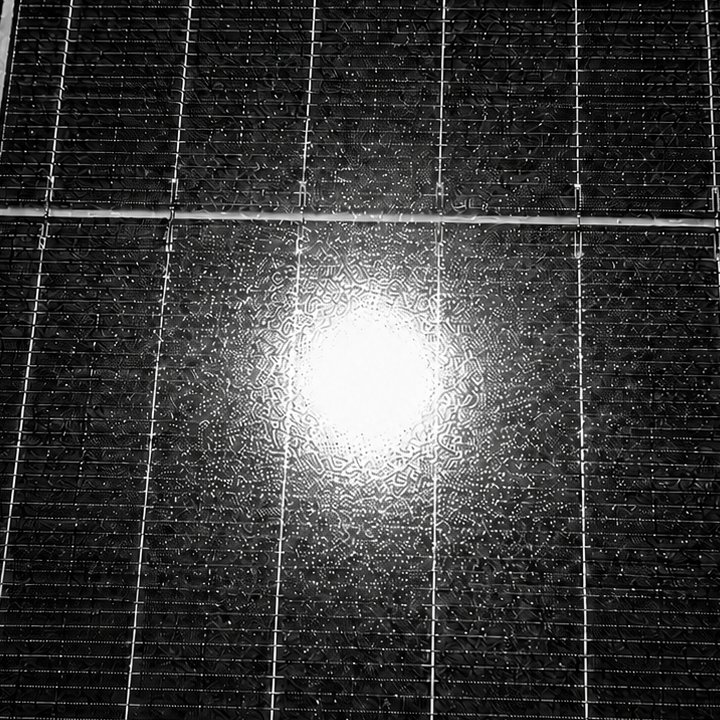
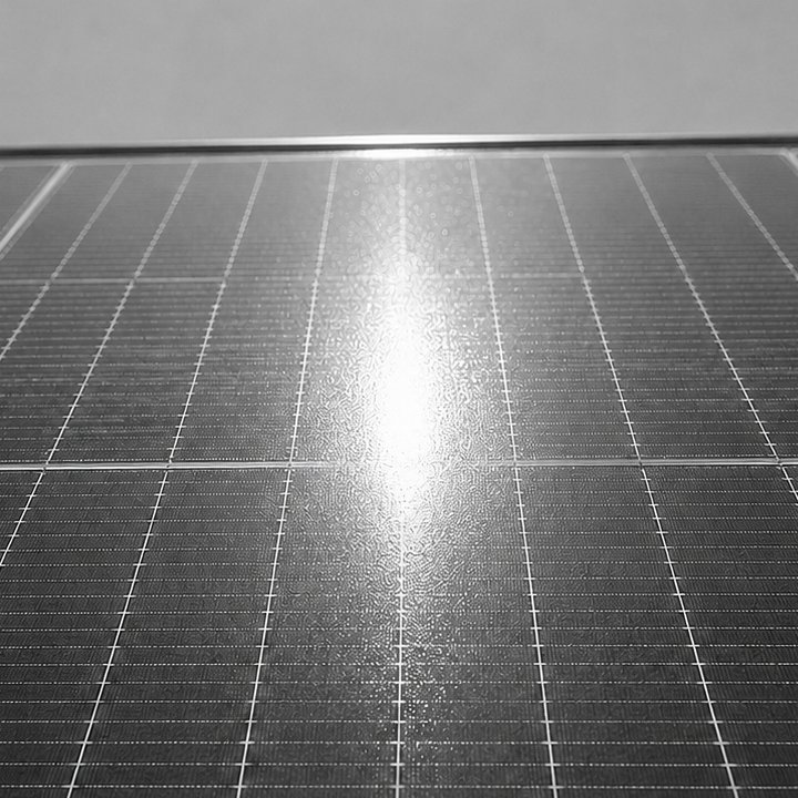
Zones. The lobe can consist of "Core", "1st ring" and "2nd ring", each zone with its own luminance and its own axes; the offset δ applies to all. Within a zone, the luminance is uniform; if a direction lies in several zones, the innermost one applies.
Perfect mirror. The system module "Perfect mirror" has no characteristic curves: the reflection has the luminance of the sun (reflectance 100 %) and only hits directions within the mirrored solar disc. It describes an upper limit of the glare effect.
How the lobe enters the hit and brightness calculation is described in Ch. V.3 and Ch. V.5.
8.3 Differences between module types
How strongly a module reflects depends mainly on the cover glass. The reflection profiles of different glasses are in some cases orders of magnitude apart.
Which glass types exist, how they glare, which system modules represent them and how a custom module type is created from test reports is described in Ch. 8.6. The system modules contain generic values for glass classes; "Phytonics Folie" is based on manufacturer data, for which no warranty is given.
Details: BRDF measurement, zones from measured values, non-specular reflection
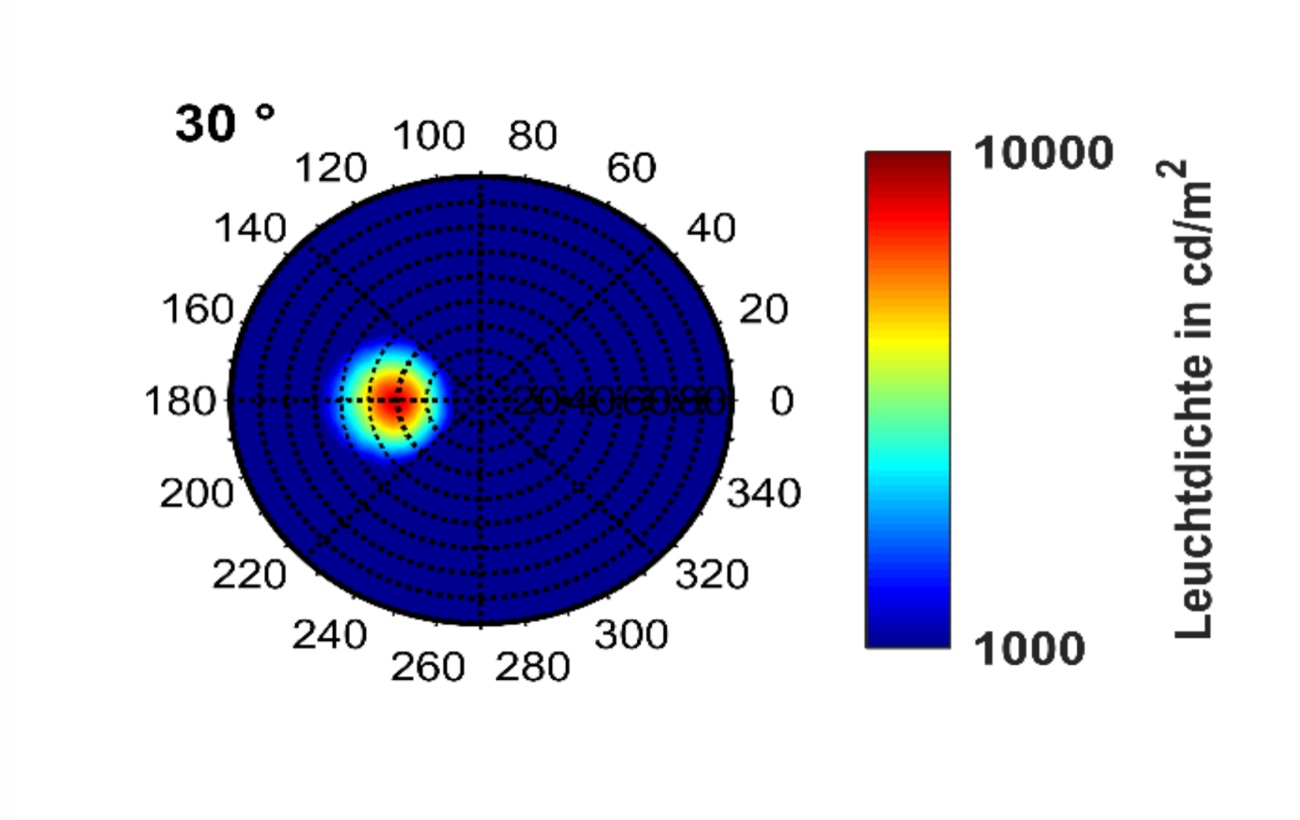
BRDF measurement. The most reliable characteristic curves come from laboratory measurements of the bidirectional reflectance distribution function (Ruesch et al. 2016; Babin et al. 2022, Ch. V.10): per angle of incidence, the maximum luminance, major and minor axis and position of the maximum (offset δ). Measurements usually do not reach 90°; values beyond are extrapolated.
Homogeneous zones. A real reflection falls off continuously towards the edge. With the maximum value applied over the whole zone cross-section, the calculated brightness tends to be too high; up to three zones reduce this overestimation. How to define zones conservatively is described in section 8.4.
Non-specular reflection. For strongly scattering glasses (e.g. satin-finish), the maximum at grazing incidence lies clearly off the mirror direction; the offset δ represents this. It can also be determined from the observed position of a glare spot.
Older module types have a single beam spread instead of two axes; the lobe is then circular.
8.4 Points to note
- No simulation starts without a module type. This also applies if the assigned module type is no longer available, e.g. a removed system module; the to-do list reports both.
- Define zones conservatively. Give each zone the luminance at its inner edge, i.e. the highest value in the zone, not an average. The steps then lie above the continuously falling measured lobe everywhere, and luminance and illuminance tend to be overestimated rather than underestimated. Place the outer edge of the outermost zone where the measurement has fallen to about 1 % of the peak: only what lies beyond this edge is underestimated, and the glare minutes depend on this edge alone. More zones bring the brightness closer to the measurement but do not change the glare minutes.
- Check measurement reports before adopting them. Measurement reports are not standardised. Above all, clarify what the 100,000 lx refer to: the module surface, as the characteristic curve here expects, or a surface perpendicular to the incident light; in the second case divide the values by cos θ_i. Different test institutes arrive at clearly different values for the same module type at shallow incidence; if in doubt, use the higher report and name the source in the note text of the module type.
- Results are fixed. The characteristic curves enter the simulation at the start; later changes to curves and zones do not change existing results (Ch. 12). Note text, manufacturer and the "outdated" flag, however, are shown in the report in their current version from the admin area.
- Deleting a custom module type sets the affected PV areas to the default module type, the first visible system module not marked as outdated.
- New module types start with example values, not the characteristic curve of a specific module. The core needs at least one luminance value greater than 0.
- Soiling, aging, moisture and snow are not represented by the module type.
8.5 Module types in the guidelines
What the guidelines say about the module is given in Ch. VI.1, Ch. VI.2 and Ch. VI.4. The key point for choosing the module type: the LAI guidance and OVE R 11-3 calculate with an ideally specular module; "Perfect mirror" reproduces this, with the sun as a disc instead of a point source. The position paper of the Federal Highway Authority (Fernstraßen-Bundesamt) requires that module-typical reflections such as beam spread be taken into account; a real module type is selected for this. Luminance thresholds from the guidelines are set in the report with the "Luminance ≥" filter (Ch. V.8).