
In brief
A field of view describes the direction in which an observer looks, for example out of a window or in the direction of travel. For each reflection, the simulation records whether it lies within the field of view and how far it is from the gaze axis. This is evaluated via the "Outside field of view" filter in the report.
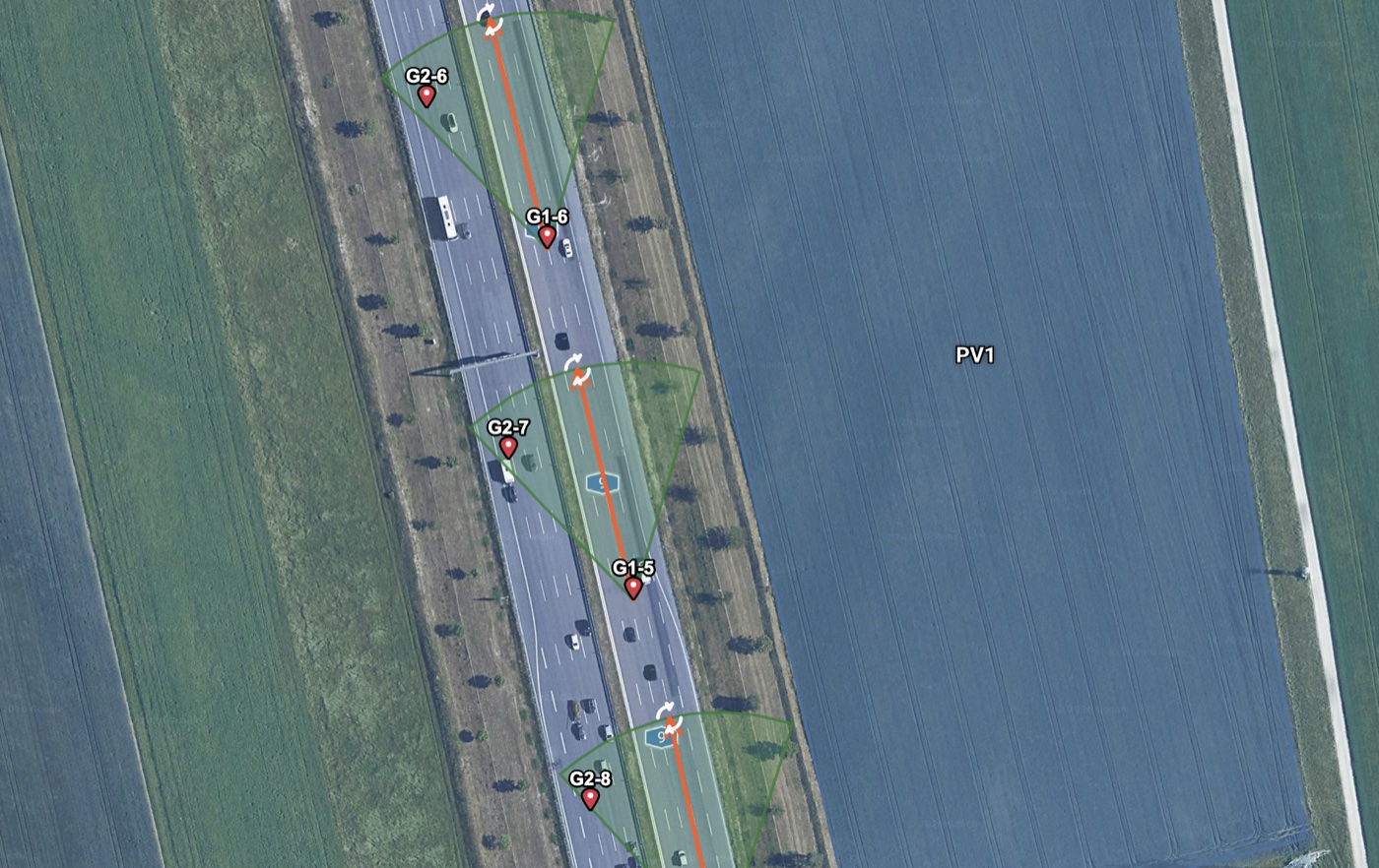
An observation point can have a field of view (FOV): a viewing direction with a horizontal and vertical opening. This represents a resident looking out of a window in a particular direction or a driver looking in the direction of travel. Without a field of view, the observation point is treated as looking in all directions.
The field of view does not restrict the calculation. The simulation calculates all reflections and records for each cell whether it lies outside the field of view; only the filter "Outside field of view" in the report removes them from the evaluation (Ch. V.8).
V.6.1 Parameters
The field of view is set per observation point in the editor and switched on with "Active" (Ch. 9):
| Field | Meaning |
|---|---|
| "Viewing Direction" | viewing direction as azimuth, 0° north, clockwise |
| "Tilt" | tilt of the viewing axis: 0° horizontal, negative values downwards (for example −3° for an approach glide path), positive upwards |
| "H±" | horizontal opening on each side of the viewing direction (half the opening angle); 30° gives a sector of 60° |
| "V-Sky" / "V-Ground" | vertical opening above and below the viewing axis |
Value ranges: "H±" 1° to 180°, "V-Sky" and "V-Ground" 1° to 90°, viewing direction 0° to 360°, tilt −90° to 90°. An opening of 0° is not permitted with an active field of view; the start checks the values and aborts if they are invalid. With "H±" 180° the field of view covers the full azimuth.
V.6.2 Check
The field of view is a rectangle in angle space (azimuth × elevation), not a cone: the horizontal and vertical limits are checked independently, and the corners fully belong to it. A calculation point lies within the field of view if
- its azimuth distance from the viewing direction is at most "H±" and
- its elevation lies between tilt − "V-Ground" and tilt + "V-Sky".
A cell only counts as outside if all its points lie outside; a cell that cuts the boundary of the field of view stays in the evaluation.
Tilt. The tilt only shifts the vertical window: at −3° (approach glide path), "V-Ground" 20° and "V-Sky" 10°, it extends from −23° to +7°. The horizontal limit remains a pure azimuth comparison and does not tilt along. The 3D perspective in the report also draws the field of view as a rectangle with this shift (Ch. 14).
Cones from guidelines. Where a guideline describes a cone around the gaze axis (section V.6.4), the rectangle is an approximation: it includes the corners outside the cone. Only the absolute distance to the gaze axis acts circularly around the axis (section V.6.3), for example in the exception "UNLESS Distance to gaze axis <".
V.6.3 Distance to the gaze axis
For observation points with a field of view, the angle between the (possibly tilted) viewing axis and the cell centre on the 0.5° grid is determined for each cell, in three ways:
| Reference | Angle |
|---|---|
| absolute | spatial angle between the tilted viewing axis and the cell centre |
| horizontal | azimuth distance from the viewing direction, independent of the tilt |
| vertical | elevation of the cell centre minus the tilt |
From this arise the figure "Min. gaze axis distance" and the exceptions "UNLESS Distance to gaze axis <" in the filters (Ch. V.8); see also Gaze-axis distance: absolute / horizontal / vertical.
V.6.4 Fields of view in the guidelines
| Guideline | Requirement | Reference | Representation |
|---|---|---|---|
| Key points paper of the Federal Highway Authority | relevant visual range ±30° horizontally around the main viewing direction, to be extended for example at merges, on-ramps and off-ramps; central visual range ±10°; on straight sections the main viewing direction follows the road | ch. 3, pp. 5–6 | "H±" 30°, viewing direction along the carriageway; distance to the gaze axis, horizontal |
| OVE R 11-3 | traffic: cone of about 30° to the main viewing direction, which follows the course of the carriageway | section 4.2, p. 9 | field of view per observation point along the route |
| RVS 05.06.11 | 30° visual cone relative to the visual or road axis (for information carriers) | sections 4.2 and 5.1, pp. 7 and 13 | field of view |
| EASA CS-ADR-DSN | visual field ranges of about 90° to each side (perception), 60° (visibility), 30° (conspicuity) and 1° to 2° (working field) | GM1 ADR-DSN.M.615 (h)(3), Issue 6, p. 162 | field of view; approach with tilted viewing axis, for example −3° |
| Rogers et al. 2015 (FAA simulator study, not a guideline) | glare sources on approach not within 50° of the straight-ahead viewing direction | DOT/FAA/AM-15/12, p. 9 | "H±" 50° (Ch. VI.4) |
| LAI guidance, OVE R 11-3 (neighbourhood) | no field of view; decisive are immission locations such as windows of protected rooms | LAI Annex 2 No. 3, p. 23 | observation points without field of view |
| EnergieSchweiz/Swissolar guide 2023 | a reflected ray is relevant only if it strikes the window more steeply than 20° | Annex 1, p. 38 | approximately via a field of view perpendicular to the window |
OVE R 11-3 and RVS 05.06.11 do not clearly specify whether a "30° cone" is to be read as the opening on each side of the viewing direction or as the total opening angle. The key points paper explicitly states ±30°. In PV-GlareCheck, "H±" is always the opening per side.