
In brief
In a tracked system, a Tracker, the modules turn about an axis during the day and follow the sun. This also means that the direction in which they reflect sunlight changes all the time. PV-GlareCheck calculates the position of the modules for every time step from the sun position and your entries for the installation. Tracked systems are a Pro feature (Ch. 3).
7.8.1 How tracking works
The modules of a tracker sit in long rows on a rotation axis, usually running north–south. In the morning they face east, at midday they lie almost flat, and in the evening they face west. The tracking angle states how far the modules are turned at a given moment; 0° means flat.
When the sun is low, the rows would shade each other. Backtracking then turns the modules back to a flatter position. So that they do not lie completely flat, they stay at least at the rest angle.
Example. Axis running north–south, "Module angle range" ±60°, backtracking with a "Rest angle" of 5°. In the morning the modules are turned towards the east, by at most 60°. Shortly after sunrise, backtracking turns them back, but not flatter than 5°. In the afternoon the same happens towards the west.
PV-GlareCheck calculates single-axis tracking: the modules turn about exactly one axis.
7.8.2 Inputs
- Create a ground-mounted area (Ch. 7.1) and choose "Tracking system (single-axis tracker)" under "Mounting type".
- Enter the "Axis orientation", i.e. the compass direction of the rotation axis: 0° means a north–south axis, 90° an east–west axis.
- Enter the "Module angle range", the maximum rotation angle to either side.
- Under "Module height above ground", enter "Top edge" and "Bottom edge" for the position at the maximum rotation angle. The editor shows the angle next to it, for example "(at 60° tilt)" (Ch. 7.4).
- Open "Tracking logic". In the "Tracking" section, set whether "Backtracking" is switched on. If so, enter "GCR" and "Rest angle".
- Set the tilt of the axis in the terrain menu (section 7.8.3).
The GCR (ground coverage ratio) is the ratio of the row width with the modules in horizontal position to the row pitch. Example: rows 2 m wide, one row every 5 m: GCR 2 / 5 = 0.4.
All tracking parameters are required. A new tracker area receives initial values (details below). If a value is missing, the to-do list reports it and the simulation does not start. PV-GlareCheck does not insert substitute values.
Details: fields, initial values and permitted values
| Field | Where | Meaning | Initial value | Permitted |
|---|---|---|---|---|
| "Axis orientation" | input fields of the area | compass direction of the rotation axis; 0° = north–south axis | 0° | 0° to 360° |
| "Module angle range" | input fields of the area | maximum rotation angle to either side | ±60° | ±10° to ±90° |
| Axis tilt ("Cross tilt") | terrain menu, step 2 | tilt of the rotation axis against the horizontal | 0° | −45° to 45° |
| "Backtracking" | "Tracking logic" | turning back when the sun is low | on | on / off |
| "GCR" | "Tracking logic" | row width / row pitch; only needed with backtracking | 0.5 | 0.01 to 1 |
| "Rest angle" | "Tracking logic" | smallest rotation angle during backtracking; only needed with backtracking | 5° | – |
Direction of the axis. 0° and 180° describe the same horizontal axis. The chosen direction, however, determines how the sign of axis tilt and tracking angle is read: a positive tracking angle turns the modules towards the side "Axis orientation" + 90°, i.e. towards the east for 0°.
7.8.3 Axis tilt from the terrain
If the installation stands on a slope, the rotation axis often follows the terrain and is then tilted. Set this axis tilt in the terrain menu. There it is called "Cross tilt", as for fixed installations, but for trackers it describes the tilt of the rotation axis.
- In the input fields of the area, click "Terrain and cross tilt" and go to "Step 2: Define cross tilt".
- Switch on "Account for cross tilt". When it is off, PV-GlareCheck calculates the axis as level.
- If "Calculate cross tilt automatically" is on, PV-GlareCheck applies the median terrain slope along the axis under the area. It is recalculated when the terrain menu is opened and after a change to the "Axis orientation". For a value from the planning documents, switch the automatic calculation off and enter the value by hand.
A positive value means that the axis descends towards the "Axis orientation". Example: "Axis orientation" 0°, the terrain falls by 3° towards the north: axis tilt +3°.
Values from −45° to 45° are permitted. Values outside this range are rejected. If the terrain gives a larger value, PV-GlareCheck adopts it and reports it; the simulation stays blocked until the value is within range. If you change the "Axis orientation" afterwards, the editor recalculates an automatic value. A value entered by hand is reported by the to-do list because it applies to the old axis; then recalculate it or keep it.
Exactly one axis tilt applies per area. "Step 3: Differentiated cross tilt" is locked for trackers. Parts of the installation on differently sloping terrain can be represented as several PV areas. Ch. 7.5 describes how the terrain heights under the area are determined.
Section 7.8.4 describes how the terrain across the axis enters backtracking.
7.8.4 How PV-GlareCheck calculates the position
For every time step of the simulation (default 1 minute), PV-GlareCheck determines the sun position at the centre of the PV area and from it the tracking angle. The angle gives the orientation of the modules at that moment and thus the direction of the reflection. All further steps run as for fixed installations (Ch. V). When the sun is below the horizon, there is no tracking angle and no reflection.
In the "Tracking curves" section under "Tracking logic", twelve curves show the tracking angle on the 21st of each month. They come from the same calculation and follow every change to the inputs. The curves are for checking and for the report (Ch. 14); they do not enter the simulation.
Deep dive: tracking angle, backtracking and rotation
- Sun position. For the tracking angle, PV-GlareCheck calculates the sun position with the Solar Position Algorithm (Reda and Andreas 2004) at the centre of the PV area at its terrain height, for every minute in standard time. The schedule (section 7.8.5), the pre-analysis (Ch. 11) and the results Excel file (Ch. 14) use the same series of minutes.
- Tracking angle. Per time step with the pvlib function for single-axis tracking, from the apparent solar zenith angle and solar azimuth, "Axis orientation", axis tilt and "Module angle range". The basis is the tracking geometry according to Lorenzo et al. (2011) and Marion and Dobos (2013).
- Backtracking. If "Backtracking" is switched on, the function turns the modules back at low sun just far enough that the rows do not shade each other at the GCR entered. The terrain across the axis is assumed to be level: a slope across the axis does not change the calculated tracking angle. Slope-aware backtracking according to Anderson and Mikofski (2020) is not applied.
- Rest angle. The rest angle is an addition by PV-GlareCheck to the pvlib function. It only acts while backtracking reduces the angle: the magnitude then does not fall below the rest angle, and the modules stay turned towards the side of the sun. It has no effect at midday.
- Axis tilt. Positive means that the axis descends towards the "Axis orientation". PV-GlareCheck calculates a negative axis tilt as the same axis in the opposite direction with a positive tilt; the sign of the tracking angle remains related to the axis orientation entered.
- Rotation. The surface normal results from rotation about the axis (Rodrigues' formula); positive angles tip it towards the side "Axis orientation" + 90°. No cross tilt across the axis is applied to trackers.
- Back side. For trackers, the check for back side and grazing view (Ch. V.3) runs per time step with the normal of that time step. In the point-by-point check it applies to every hit calculation point. On the cell grid the cell centre decides; if the boundary runs through the cell, its calculation points decide: the cell remains as soon as one of them is in front, and carries only the solid angle of the points in front.
- Missing values. Without complete tracking parameters, the simulation does not start (section 7.8.2).
7.8.5 Custom schedule
A schedule lets you specify a different set angle from the calculated tracking for individual minutes, for example for a glare-reducing control strategy. In all other minutes, the simulation calculates according to the parameters. Download the schedule as an Excel file in the "Schedule" section under "Tracking logic", change only the "Setpoint" column and upload it again. If you then change the location, time zone or tracking parameters of the area, the to-do list blocks the start until you download and upload the schedule again or remove it.
Details: schedule step by step, checks and validity
- Download: Open "Tracking logic" and, in the "Schedule" section, choose "Download schedule (Excel)". The file contains one row for each minute with the sun above the horizon: the date without the year, the time in standard time, the calculated angle (locked) and the "Setpoint" column. If a schedule is already active, the file contains its setpoints, so you can edit it further.
- Adjust: Change only the "Setpoint" column.
- Upload: Choose "Upload adjusted schedule". PV-GlareCheck checks the whole file; the message lists any errors with the row number.
- Check: The panel then shows how many minutes on how many days have been adjusted and the largest deviation, together with the file name.
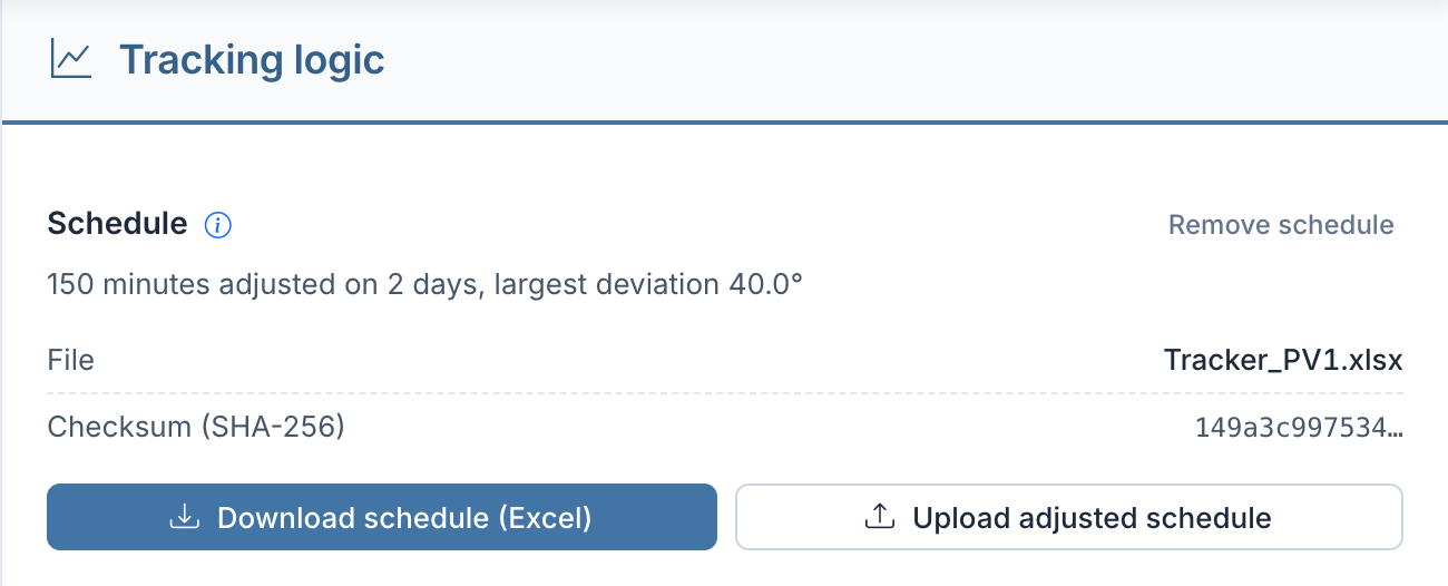
"Remove schedule" asks for confirmation and then restores tracking according to the parameters. The report and the results Excel file state the schedule (Ch. 14).
Checks on upload. PV-GlareCheck rejects the file if - it is not a readable Excel file or is too large (at most 25 MB), - it belongs to another project or area, - the area settings were changed after the download (check key on the "Info" sheet), - no setpoint differs from the calculated angle; the file is then not taken over as a schedule, and an existing schedule remains.
The message lists errors in individual rows with the row number: setpoint empty, not a number, a formula without a calculated value or larger than the angle range; invalid date or time; minute duplicated, out of chronological order or without the sun above the horizon. It lists missing minutes with their date and time. Setpoints are taken over to 0.01°.
Validity. A schedule is only valid for the location, time zone and tracking parameters it was downloaded with. If any of them changes, the to-do list blocks the simulation until the schedule is downloaded and uploaded again or removed. A replaced or removed file is deleted as soon as no simulation and no saved version refers to it. As long as a saved version contains the schedule, the file is kept.
7.8.6 Fault and special positions
The simulation tracks the modules according to the parameters and, where present, the schedule. It does not by itself calculate positions outside this operation, such as a stow, wind or snow protection position or a fault position.
Important: Fault and special positions, for example raised modules in agrivoltaics during cultivation or a wind or snow protection position, should be checked with a separate area configuration, for instance as a fixed-mount area with the corresponding parameters.
Such a position can be calculated as a separate version of the project (Ch. 4); the batch analysis does not vary tracker areas (Ch. 13). If the position lies within the angle range and it is known in which minutes it applies, it can also be represented by a schedule (section 7.8.5).
Details: position as a fixed area
With a horizontal axis, a set angle θ corresponds to a fixed-mount area with the tilt |θ|. The modules then face the side "Axis orientation" + 90° if θ is positive, otherwise the side "Axis orientation" − 90°.
Example. North–south axis ("Axis orientation" 0°), position +60°: fixed area with "Azimuth" 90° and "Tilt" 60°. Enter "Top edge" and "Bottom edge" for exactly this position (Ch. 7.4).
7.8.7 Limits
- One control per area. All modules of a PV area turn the same way: with the same tracking parameters and the same schedule. Rows with a different control can be represented as separate PV areas.
- One axis tilt per area. There are no zones with their own axis tilt (section 7.8.3).
- Terrain across the axis level. See section 7.8.4, backtracking.
- No special positions in the calculation. The simulation only calculates fault and special positions such as stow, wind or snow protection positions if you represent them separately (section 7.8.6).
Ch. VII.3 describes further limits of the model, including for trackers.
7.8.8 Sources
The tracking geometry follows Lorenzo, Narvarte and Muñoz (2011) and Marion and Dobos (2013); the calculation uses pvlib (Holmgren, Hansen and Mikofski 2018). The sun position follows the Solar Position Algorithm according to Reda and Andreas (2004). Slope-aware backtracking according to Anderson and Mikofski (2020) is not applied. The full references are in Ch. E.